Data Reduction Schema

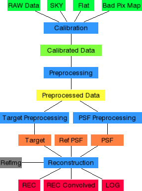
The LINC-NIRVANA Data Reduction Software (LN DRS) implements a data reduction and image reconstruction pipeline (see figure 1). The software provides all steps necessary to reconstruct high-resolution images from several LINC-NIRVANA raw images. The flowchart in figure 1 represents the data flow (from top to bottom).

Data reduction and image reconstruction pipeline

Two different elements are shown in the flowchart. The blue rectangles represent data reduction and reconstruction steps; the other rectangles represent files with specific content. The processing steps are executed in the following order:

  1. Calibration: compensates detector and instrument effects like flatfield and bad pixels.
  2. Preprocessing: compensates observation effects like image rotation.
  3. Target Preprocessing: extracts the target from the preprocessed data.
  4. PSF Preprocessing: extracts the psf from the preprocessed data and removes the background.
  5. Reconstruction: reconstructs an image from target and psf images.

The LN DRS uses the files with the following content:

  • RAW Data: the raw interferograms of the science target from the LINC-NIRVANA instrument.
  • SKY: sky images.
  • Flat: the flatfield map for compensating the pixel gain.
  • Bad Pix Map: a map in which all defective pixels are marked as bad pixels.
  • Calibrated Data: the calibrated interferograms (without instrument effects).
  • Preprocessed data: the preprocessed interferograms (without observational effects).
  • Target: the extracted target.
  • Ref PSF: the reference psf (23m).
  • PSF: the extracted psf.
  • RefImg: the convolved reference image for calculating the image error (used for the tests).
  • REC: the reconstruction (not convolved).
  • REC Convolved: the convolved (23m psf) reconstructed object.
  • LOG: the file with logging information.
Figure 1: The flowchart represents the data reduction and image reconstruction pipeline.

An astronomer collects raw data images and calibration data (sky, flatfield and bad pixel map) from an observation and can use the graphical user interface to inspect these data and parameterize the pipeline. By executing the pipeline, controlled by these parameters, a high resolution image will be reconstructed.

Downloading the Software

The software of the LINC-NIRVANA Data Reduction System (LN DRS) uses the IDL programming language and consists of several components:

  1. The idlastro library (mandatory) idlastro.tar.gz (4.7MB)
  2. The LN DRS package itself (mandatory) lndrs.tar.gz (65KB)
  3. The LN DRS documentation (HTML, optional) lndrs_manual.tar.gz (2.1MB)
  4. An example (NGC4151, optional) NGC4151.tar.gz (121MB)
  5. A configuration file editor written in Java (optional) lndrs.jar (54KB)

Please download at least the first two packages from the web page at http://www.mpifr-bonn.mpg.de/lndrs/index.html and store them in a proper directory (e.g. ~/lndrs).

Installing the Software

After downloading all packages into a directory (e.g. ~/lndrs), please go into this directory and follow these steps:

  1. Unpack the idlastro library package with the command
    tar xzf idlastro.tar.gz
    A subdirectory with the name idlastro is created.
  2. If you use the bash as your shell, then include
    export IDL_PATH="<IDL_DEFAULT>:~/lndrs/idlastro/pro"
    in your .bash_profile file. If you are using the tcsh, then include
    setenv IDL_PATH "<IDL_DEFAULT>:~/lndrs/idlastro/pro"
    in your .cshrc file.
    If you want to use the software from within any directory, you must add the source code directory (e.g. ~/lndrs/idl) to the environment variable.
  3. Unpack the LN DRS package with the command
    tar xzf lndrs.tar.gz
    A subdirectory with the name idl is created.
  4. If you downloaded the example file, unpack it with the command
    tar xzf NGC4151.tar.gz
    A subdirectory NGC4151 is created with all input files of a data reduction example.

Documentation

Table of Contents

List of Figures

  1. The flowchart represents the data reduction and image reconstruction pipeline.
  2. The main window of the LN DRS (left panel) represents the pipeline (flowchart in the left window) and provides access to the available algorithms and selected files. The image window of the LN DRS (right panel) shows loaded images and provides access to specific tools.
  3. Window, menu and dialog box to load a parameter set.
  4. Load an existing image.
  5. A loaded image is shown in the LN DRS Image GUI window.
  6. Performing a calibration.
  7. Calibrated data.
  8. Preprocessing.
  9. The image window shows the first preprocessed interferogram (for the first position angle).
  10. The algorithm-specific target creation setup dialog.
  11. The target image created from the target preprocessing step.
  12. The algorithm-specific psf creation setup dialog.
  13. The psf image created from the psf preprocessing step.
  14. The algorithm-specific reconstruction setup dialog.
  15. The reconstructed target convolved with the reference psf (23m psf).
  16. Configuration editor.
  17. A loaded image is shown in the LN DRS Image GUI window.
  18. Toolbar in the LN DRS Image GUI window.
  19. Graphical representation and dialog window of an image probe.
  20. Graphical representation and dialog window of an image pixel.
  21. Standard calibration setup dialog.
  22. Dialog window containing the preprocessing parameters.
  23. Calibrated data.
  24. Graphical representation and dialog window of a reference star.
  25. Preprocessed interferogram with a target object, two psf stars and an image probe.
  26. Graphical representation and dialog window of a target.
  27. The algorithm-specific target creation setup dialog.
  28. The target image created from the target preprocessing step.
  29. Preprocessed interferogram with a target object, two psf stars and an image probe.
  30. Graphical representation and dialog window of a psf star.
  31. Graphical representation and dialog window of a target halo.
  32. The algorithm-specific psf creation setup dialog.
  33. The psf image created from the psf preprocessing step.
  34. Left panel: a typical target used by the Richardson-Lucy deconvolution algorithm. Right panel: the associated psf.
  35. Setup dialog window for the Richardson-Lucy algorithm.
  36. Left panel: a reconstructed target using the Richardson-Lucy deconvolution algorithm. Right panel: the same image convolved with an ideal 23m psf.
  37. Class hierarchy of the framework core classes.
  38. Properties and dependencies of the framework core classes.

List of Tables

  1. Optional arguments for the GUI command.
  2. Optional arguments for the pipeline command.
  3. Predefined tools
  4. View tool mouse button assignment
  5. Info tool mouse button assignment
  6. Probe tool mouse button assignment
  7. Pixel tool mouse button assignment
  8. Reference star tool mouse button assignment
  9. Target tool mouse button assignment
  10. Psf star tool mouse button assignment
  11. Halo tool mouse button assignment
  12. Tool template placeholders
  13. Properties of the reconstruction step in the configuration file.

List of Sources

  1. Invoking the pipeline from a shell script.
  2. Invoking the pipeline from an IDL startup file.
  3. Invoking the pipeline from the IDL command prompt.
  4. Code snippet for calculating the rotation angle.
  5. Code snippet for calcuating the translation vector.
  6. IDL template for a tool.
  7. Excerpt from the configuration file for a tool.
  8. Snippet from the configuration file concerning recentering.
  9. Recentering method template.
  10. Part of a configuration file concerning a new recentering method.
  11. Excerpt of code for recentering using the intensity peak.
  12. Excerpt of code for recentering using the intensity mean.
  13. Excerpt of code for recentering using the fourier phase.
  14. Excerpt from the configuration file concerning the sky background.
  15. Excerpt from the configuration file concerning the defective pixel interpolation.
  16. Defective pixel interpolation method template.
  17. Part of a configuration file concerning a new defective pixel interpolation.
  18. Determine the pixel pairs.
  19. Calculate the replacement values.
  20. Replacing the value of a defective pixel.
  21. Excerpt from the configuration file concerning the reconstruction step.