 |
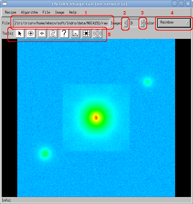
After loading a file, the contents are shown in the LN DRS Image GUI window (see figure 1). If the file contains several images (several position angles), the first image is displayed.
 |
This window provides the following functional interface:
The toolbar in the image window (see figure 2 and table 1) provides tools for navigating a loaded image, getting information about a part of an image or creating and modifying objects necessary for specific data processing steps (for example, creating reference stars for the preprocessing step).
 |
Except for the view tool and the info tool, each tool has an accompanying object which is created, manipulated and deleted through that tool.
| Icon | Name | Description |
|---|---|---|
 | View tool | Provides functions for zooming and panning images. |
 | Reference star tool | Provides functions for creating and modifying reference stars (preprocessing step). |
 | PSF star tool | Provides functions for creating and modifying psf stars (psf preprocessing step). |
 | Target tool | Provides functions for creating and modifying targets (target preprocessing step). |
 | Info tool | Provides access to created objects and their specification. |
 | Probe tool | Provides statistical information of an image part. |
| Pixel tool | Provides information about an individual pixel and its direct neighbours. | |
 | Halo tool | Creates and modifies a target halo (psf preprocessing). |
This tool provides functions for zooming and panning (moving) an image in the LN DRS Image GUI window. Other tools also include this function, but the Shift key must be pressed simultaneously.
| Button | Function |
|---|---|
| Left click | Zooms into the image and the click position is used as the new image center. |
| Middle click | Uses the click position as the new image center. |
| Right click | Zooms out of the image and the click position is used as the new image center. |
| Middle drag | Moves the image. |
The zoom function is equivalent to binning or enlarging pixels. The zoom steps are integral values. This means that the values go from -20 to 20, where positive numbers mean enlarging (zooming in) and negative values shrinking (binning). A value of 0 means a 1:1 image display.
The info tool provides access to the information of graphical objects. By selecting this tool and an existing object with the left mouse button, the dialog window containing the object-specific data is shown. In addition, the functionality of the view tool is still available by pressing the shift key simultaneously with a mouse button.
| Mouse button | Function |
|---|---|
| Left click | Shows the dialog window containing information about the selected object. |
| Shift left click | Zooms into the image and the click position is used as the new image center (from view tool). |
| Shift middle click | Uses the click position as the new image center (from view tool). |
| Shift right click | Zooms out of the image and the click position is used as the new image center (from view tool). |
| Shift middle drag | Moves the image (from view tool). |
The probe tool allows the creation and modification of image probes. These probes define an image part and show statistical information about that part. The primary purpose of an image probe is to give information about the background.
| Mouse button | Function |
|---|---|
| Left click | Creates a new image probe at the mouse position. |
| Middle click | Shows the dialog window containing all information about the selected image probe. |
| Right click | Deletes the selected image probe. |
| Control left click | Enlarges the size of the selected image probe by a factor of two. |
| Control right click | Shrinks the size of the selected image probe by a factor of two. |
| Middle drag | Moves the selected image probe to a different position. |
| Shift left click | Zooms into the image and the click position is used as the new image center (from view tool). |
| Shift middle click | Uses the click position as the new image center (from view tool). |
| Shift right click | Zooms out of the image and the click position is used as the new image center (from view tool). |
| Shift middle drag | Moves the image (from view tool). |
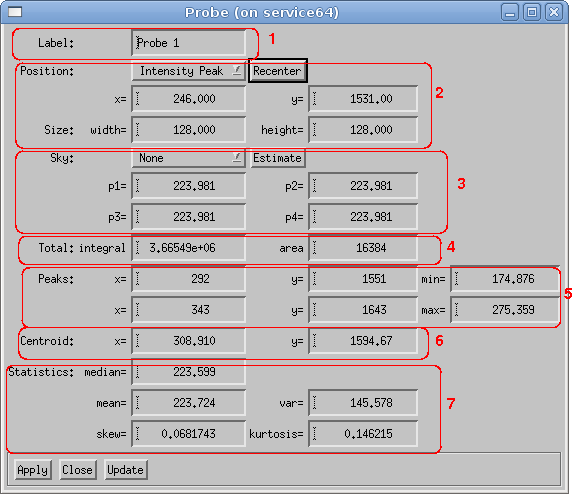
Figure 3 shows the the graphical representation of an image probe and the dialog window with the statistical information. It is possible to automatically recenter the image probe by using the intensity peak, intensity mean or fourier phase (see section Recentering objects).
 |  |
The dialog window of an image probe shows the following information:
The pixel tool and the accompanying pixel object shows information about one pixel and compares the value to the nearest eight pixels.
| Mouse button | Function |
|---|---|
| Left click | Creates a new pixel probe at the mouse position. |
| Middle click | Shows the dialog window containing all information about the selected pixel. |
| Right click | Deletes the selected pixel probe. |
| Middle drag | Moves the selected pixel probe to a different position. |
| Shift left click | Zooms into the image and the click position is used as the new image center (from view tool). |
| Shift middle click | Uses the click position as the new image center (from view tool). |
| Shift right click | Zooms out of the image and the click position is used as the new image center (from view tool). |
| Shift middle drag | Moves the image (from view tool). |
Figure 4 shows the graphical representation of a pixel probe and the dialog window with the statistical information. It is possible to automatically recenter the pixel probe by using the intensity peak, intensity mean or fourier phase (see section Recentering objects).
The dialog window of an image pixel shows the following information: