Back to receiver page   Back to the SMT receiver page


The MPIfR 19-channel bolometer array

In March 2000, a 19-channel bolometer array, developed at the MPIfR Bonn by E. Kreysa and collaborators, was installed at the HHT. It consists of 19 individual broadband continuum receivers, and is sensitive around a wavelength of 0.87mm (345GHz).

On this page we compile some information about this bolometer array, coming partially from test observations carried out in April/May 2000.

Array Layout
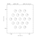
The 19 channels are arranged in two concentric hexagons around the central channel. The figure to the right shows the array geometry at an elevation of 0 degrees. The azimuth distance between two adjacent channels is about 50", and the maximum beam separation about 200". The channel numbers indicate the location on which the source will appear in this channel when the central channel is centered on the source (to get the actual position of the channels on the sky, you have to rotate the whole picture by 180 degree). For increasing elevations, the image of the whole array rotates counter-clockwise on the sky. Array layout

Bandpass
The bandpass of a bolometer is usually not a flat profile. The small figure to the right shows the sensitivity of the central channel of the 19-channel array as a function of frequency. To get the response of the instrument to any astronomical signal, you have to multiply this curve with the atmospheric transmission. Bolometer bandpass

Sensitivity
In the submillimeter range, most of the noise is due to the atmosphere. With proper data reduction, this atmospheric noise can be eliminated to a certain degree. The remaining noise level is about
600 mJy (second)-1/2 per channel
Note that this value includes already the amount of observing time spent on a reference position (blank sky) using the wobbling secondary. The pure instrumental sensitivity is therefore a factor sqrt(2) better.

Even if this value is still preliminary, it can serve to estimate the observing time needed.

  • On-Off: This procedure should be used for point sources (flux measurements, detection experiments, ...). The necessary observing time can easily be calculated with the number above, e.g. to reach an rms noise of 6 mJy, you should expect to observe for (600/6)2 seconds, i.e. about 3 hours.
  • On-The-Fly: Extended sources should be mapped. Consult the SMTO User Manual for necessary map sizes. With a scanning velocity of 8" per second (which means about 40 minutes per 400" x 300" map) you can expect an rms noise of 150 mJy/beam per coverage (i.e. after co-adding the 19 channels).
We again emphasize that these values include already the amount of time spent off-source using the wobbler, and also the elimination of correlated atmospheric noise during data reduction!

Remember that you have to add a certain overhead to the integration times estimated. Pointing and focus measurements, as well as maps of planets and skydip measurements for calibration purposes, may add up to 25 percent or more of the total estimated integration time

Data Reduction
The reduction of data taken with the bolometer can currently be done by two individual programs, MOPSI and NIC. MOPSI is developed by Robert Zylka (MPIfR Bonn/ITA Heidelberg) and can read the telescope raw data directly. The output format is NOD2. NIC is part of the Gildas software package and is mainly developed at IRAM Grenoble. It reads the Ascii-NMB data format, which is produced on-site by the HHT2NIC program, and writes the output in GDF format, which can be further processed by the GRAPHIC program.


Last changed: November 3, 2000
Contact: Michael Dumke (mdumke@as.arizona.edu).