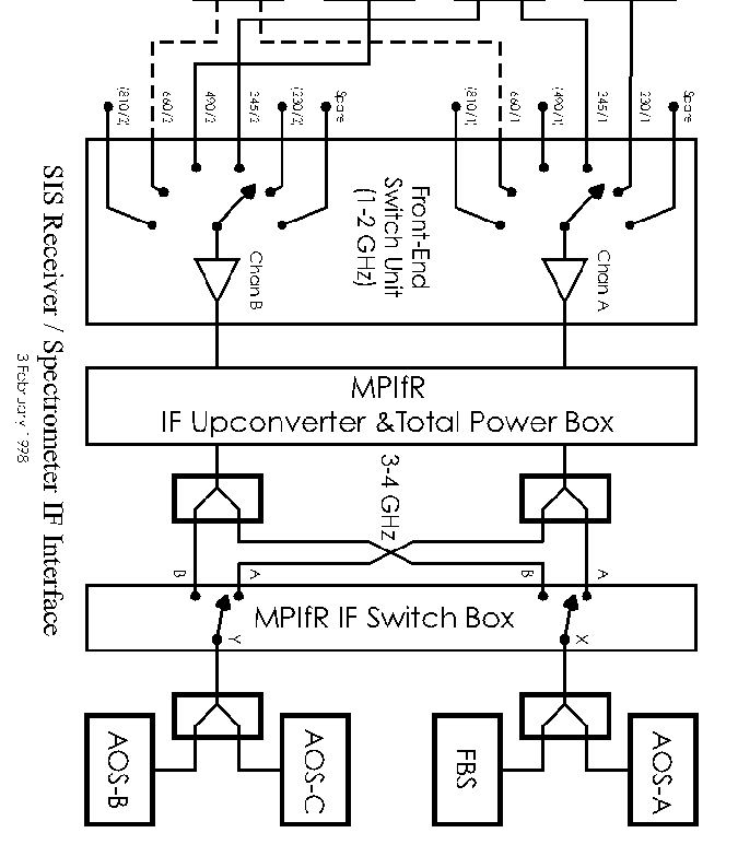
In January 1997, we installed a new Receiver/Spectrometer IF interface. It allows computer control of the receiver and spectrometers desired. Figure 5.1 shows the current setup for how all the facility receivers are connected up to the AOSs and FBS.
If you go upstairs to the facility receiver cabin, you will see a little box that has two sets of lights on the optical bench that holds our facility receivers. The top set refers to Chan A (IF 1) in figure 5.1 and the bottom set refers to Chan B (IF 2). On the left side of the box is the selected IF (coded in terms of SIS 230 or SIS 345). This has to reflect the correct IF selection.
The MPifR IF converter and Total Power Box as well as the MPifR switch box are located above the cooled rack in the computer room. The system is under full computer control, (though we can go to local mode if absolutely necessary). The switches must be set to match either Chan A (IF 1) or Chan B (IF 2) to the X and Y switches. Normally, Chan A (IF 1) connects to X and Chan B (IF 2) connects to Y.
This means that whatever is hooked up on IF 1 (CHAN A) will be seen by AOSA and FBS, and whatever is hooked up on IF 2 (Chan B) will be seen by AOSB and AOSC.
Figure 5.2 reveals how Chan A and Chan B, Backend switch X and Y will have to be set to achieve the desired receiver/backend configuration. In general, however, the observer controls this through the computer - and never touches a switch!