Polyhedra with the Zometool
"Thus, the chief reason for studying regular polyhedra is still the same as in
the time of the Pythagoreans, namely, that their symmetrical shapes appeal to one's
artistic sense."
H. S. M. Coxeter, in the preface to "Regular Polytopes".
In Figs. 3.3a, b and c, we have seen three models of polyhedra built with the Zometool.
Such edge models display only the vertex and edge arrangements; unlike paper models they
cannot display face
arrangements. A consequence of this is that the Icosahedron and the Great
dodecahedron, which share the same edge arrangements, are represented by the same edge
model. The same happens for the Stellated dodecahedron and the Great icosahedron. The
ditrigonal polyhedra in Fig. 3.7 and the Compound of five cubes in Fig. 3.8b share the
same edge arrangement and thus the same edge model.
However, this can also be an advantage: because they don't display the faces, they allow
the display of internal structure. For the models that follow that is absolutely
necessary. As an example, the first two models below represent the five Platonic solids.
However, they are not represented in isolation (something that would merely repeat the paper models above), but instead in an arrangement that
illustrates many interesting geometric relations between them, in a very elegant and
economic way. Clearly, such a model cannot be made with paper. The first model in
particular was the first kit of the Zometool I purchased; it was especially useful for me
to familiarise myself with the interesting properties of the system.
The Tetrahedron and Octahedron are built with G struts; the other regular polyhedra are
built with B struts. These colours are the same for their rectifications: for instance,
the Octahedron is built with G struts like the Tetrahedron, the Cuboctahedron is built
with G struts like the Octahedron (not B struts as the Cube); the Icosidodecahedron is
built with B struts like the Icosahedron or Dodecahedron. The reason for this can be seen
in Fig. 2.4d, where each Pentagonal face of the Dodecahedron is rectified into a smaller
Pentagon.
Most models in this page (but not the following pages on polychora) have G or B struts
with non-native colours. These can be purchased from the Zometool company on demand, but
they are slightly more expensive than struts in native colours. They are used here to help
distinguish the regular polyhedra from each other. Except where stated, these were
designed by myself.
Fundamental models
We now present a set of models that illustrate some fundamental properties of polyhedra
and of the Zomeool.
The model in Fig. 4.1a includes models of the five Platonic solids. This is a kit sold by
the Zometool company with the name ``Kepler's Obsession''. This
was designed by John H. Conway, who called it
his ``Cosmogram''. It is not Kepler's polyhedral model of the
Solar System published in his Mysterium Cosmographicum, but it bears some resemblance,
hence its name. Fig. 4.1b shows a one size larger version I have built. With the Zometool
it is always possible to re-scale models because of the inherent scalability of the
system, which is due ultimately to its use of the Golden ratio.
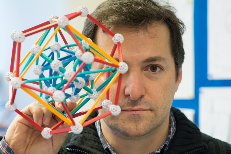
Fig. 4.1a: Myself holding a beautiful geometrical model sold by the Zometool company as
Kepler's Obsession. Photo by Aris Noutsos.
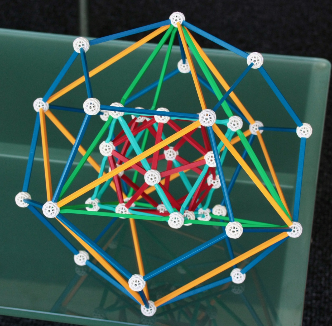
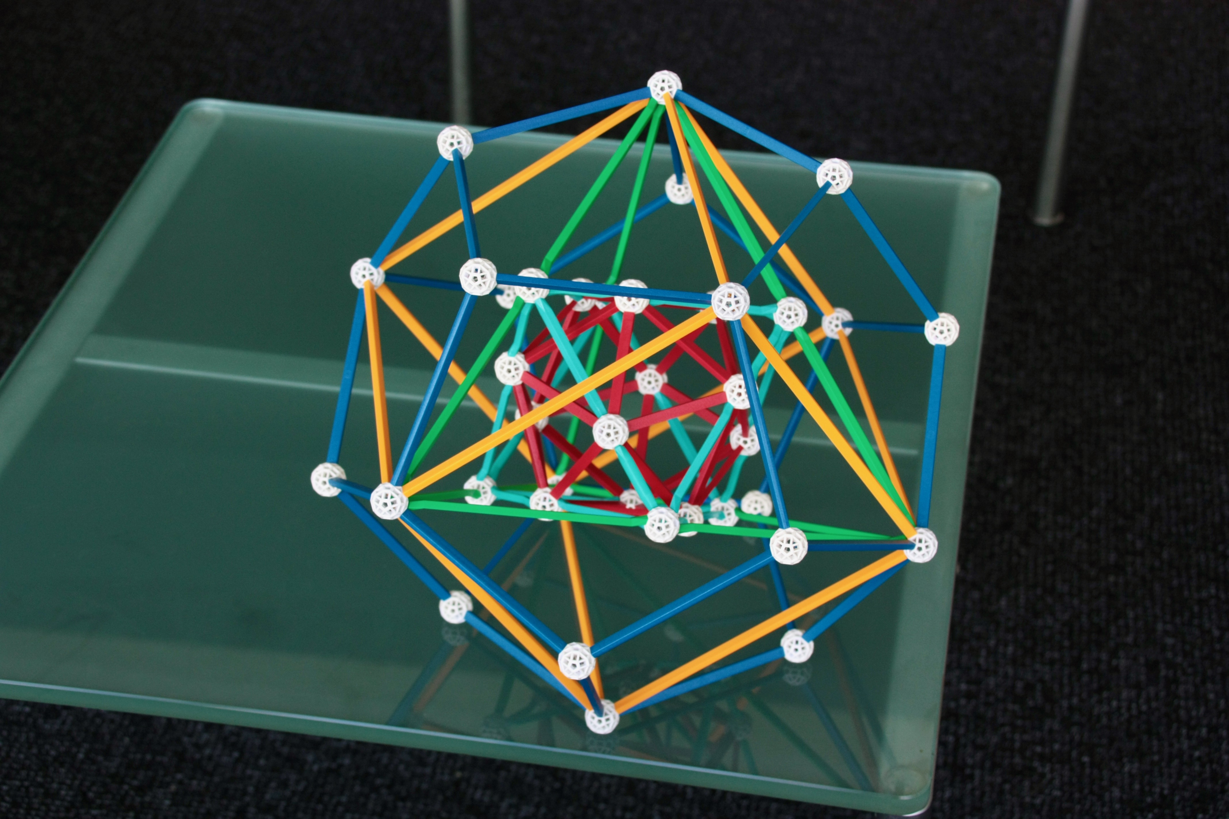
Fig. 4.1b: This is a larger version of the model above, which I have made using some of
the specially coloured struts from the model above and other rare parts of the Zometool*.
The innermost polyhedron, the Icosahedron (represented in the model in Fig. 4.1b by the
red B1 struts) is the dual of the outermost polyhedron, the Dodecahedron (dark blue B2
struts). The second-innermost polyhedron, the Octahedron (light blue HG1 and HG2 struts)
is the dual of the second outermost one, the Cube (yellow B3 struts). The middle
polyhedron, the Tetrahedron (green HG3 struts) is self-dual. The model is put together in
such a way that each vertex of a polyhedron lines up with the face of its dual, and
vice-versa; furthermore, the edges of dual polyhedra are perpendicular to each other. An
interesting implication of this is that the whole model is, in a way, also self-dual!
Also,
- The 12 vertices of the Icosahedron touch the 12 edges of the Octahedron.
- The 6 vertices of the Octahedron touch, in their midpoints, the 6 edges of the Tetrahedron.
- The 6 edges of the Tetrahedron are diagonals of the 6 Square faces of the Cube.
- The 12 edges of the Cube are diagonals of the 12 Pentagonal faces of the Dodecahedron.
Thus, when the vertex of an inner polyhedron A touches and edge of inner polyhedron B, the
edge of the dual of B is a diagonal of the face of the dual of A. The construction is
possible because the number of vertices of the Octahedron (6) and Icosahedron (12) are the
same as the number of edges of the Tetrahedron (6) and Octahedron (12) - by duality, the 6
and 12 edges of the Tetrahedron and Cube correspond to the 6 and 12 faces of the Cube and
Dodecahedron.
Challenge to the reader: The numerical coincidence of vertices of the Octahedron
and edges of the Tetrahedron is easily explained: the Octahedron is the rectification of
the Tetrahedron (see previous page).
However, is there any special reason why the number of vertices of the Icosahedron (12)
has to be the same as the number of edges of the Octahedron? (An answer is provided in
the caption of Fig. 5.7).
We can also see that:
- The 8 faces of the Octahedron are in the same planes as 8 of the 20 faces of the
Icosahedron.
- The 4 facial planes of the Tetrahedron coincide with 4 of the 8 facial planes of the
Octahedron.
- The 4 vertices of this Tetrahedron coincide with 4 of the 8 vertices of the Cube (i.e.,
the Tetrahedron is "inscribed" in the Cube).
- The 8 vertices of the Cube coincide with 8 of the 20 vertices of an outer Dodecahedron
(i.e., the Cube is inscribed in the Dodecahedron).
Thus, the facial plane coincidences of the inner polyhedra - all of them with Triangular
faces - are the duals of the vertex coincidences of the outer polyhedra - all of them with
Triangular vertex figures. These vertex coincidences are explored in Figs. 4.3a, b and c.
Many other things can be seen in the model. For instance, if we extend the edges of the
inner Icosahedron, they meet two vertices of the outer Dodecahedron. The edge arrangement
would then be that of the Great stellated dodecahedron. Also, all the edges of the inner
Octahedron do this as well, but only in one direction!
The models above have no mirror symmetry; only a type of symmetry called
chiral Tetrahedral symmetry. To achieve mirror symmetry, we would need to add a second
Tetrahedron, the dual to the one in the model, making a Stella Octangula configuration
(Fig. 3.8a and 4.5a, b below). Then, we'd have a complete stellation of the Octahedron and
a complete faceting of the Cube in this model. The resulting model would then have an
overall
pyritohedral symmetry. This is an important symmetry that occurs often: it is similar
to the Octahedral, except that around the 3-fold symmetry axes there is no reflection
symmetry, only rotational symmetry, consequently the axes of 4-fold symmetry become axes
of 2-fold symmetry, and there is only central symmetry for the previous axes of 2-fold
symmetry that went through the edges of the Cube/Octahedron. Part of the reason why it
occurs often is that it is a subgroup of the Icosahedral symmetry.
To go from the pyritohedral to Icosahedral symmetry, we rotate the pyritohedric version of
the model in Fig. 9.1b four times around a 5-fold axis of the Icosahedron/Dodecahedron,
and superpose these to the original - a process we will call here "Quintuplication" and
will use often. After the quintuplication, we find that the inner Icosahedron stays
unchanged, the Octahedron becomes a Compound of five octahedra (illustrating how it
results from a stellation of the Icosahedron), the Stella Octangula becomes a Compound of
ten tetrahedra (illustrating how the latter compound results from a stellation of the
Icosahedron, being self-dual it is also a faceting of the Dodecahedron), the Cube becomes
a Compound of 5 Cubes (illustrating how it results from the faceting of a Dodecahedron,
this is the dual of the inner Compound of five octahedra) and the outermost Dodecahedron
(the dual of the innermost Icosahedron) stays the same. All of these facetings and
stellations are shown in the models below.
* Some words on this. The model in Fig. 4.1b represents an improvement compared to
the model in Fig. 4.1a because:
a) each polyhedron is now represented by a different colour: in Fig. 4.1a, the
Octahedron and the Tetrahedron are in the same colour, blue-green. That error (later fixed
by the Zometool company) was useful: I used the 12 extremely rare light blue HG2 struts of
the Tetrahedron in 4.1a to build the larger Octahedron in 4.1b.
b) The edges of this Octahedron are no longer dominated by the twists of the HG
parts.
The inner Icosahedron in 4.1b is made with the red B1 struts of the outer
Dodecahedron in 4.1a. The outer Dodecahedron in 4.1b is made using commonplace B2 struts.
For the Cube in 4.1b, I've had for a long time the rare yellow B3 equivalents of the
yellow B2 struts in 4.1a. What finally made the model in 4.1b possible was the surprise
inclusion of a set of extremely rare green HG3 struts in a large lot of the Zometool parts
I have purchased in 2019, these are used to make the Tetrahedron.
I like the colour scheme of the model in Fig. 4.1b very much. The colours of the dual
pairs are opposed: If we associate these colours with a sequence in the Rainbow (red,
yellow, green, blue-green, dark blue/violet), then the inner/outer solids have the
extremes of the sequence, the middle solid has the middle colour (green) and the others
have the remaining, not-so-extreme colours. Relative to Fig. 4.1a, the colours of the
inner/outer pair were exchanged, something that increases the contrast between polyhedra
and makes it easier to distinguish them.
***
I now show several models from which the metric properties of the regular polyhedra and
Icosidodecahedron, and even their vertex coordinates, can be easily inferred (this is left
to the interested reader as an exercise). These don't include the Octahedron, for which
these properties can be inferred from its equatorial Square. In these models, the struts
connecting the figures to their centres will be designated as "radials".

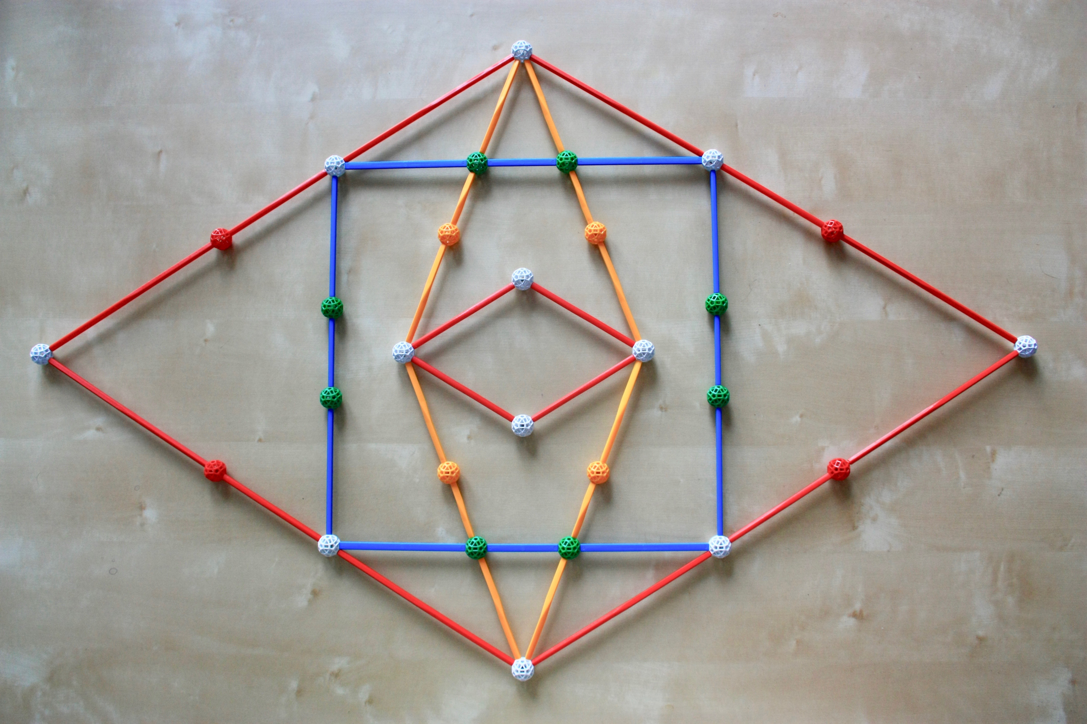
Fig. 4.2: Three orthogonal Golden triangles, in a configuration with pyritohedric symmetry.
The vertices are those of the Icosahedron.
The first is a set of three Golden rectanges (prepresented by the B1 and B2 struts),
together with the radials represented by the red R1 struts, as shown in Fig. 2.2d. These
rectangles are arranged along perpendicular planes in such a way that the overall
arrangement has pyritohedral symmetry. The object has a total of 4 vertices for each of
the three rectangles, thus a total of 12 vertices, and a total of 12 radial R1 struts.
These connect to the full set of 12 pentagonal holes of the central ball. The rectangles
are arranged to each other as Borromean rings.
It should be clear that the vertices of these rectangles are those of the Icosahedron. The
B1 struts represent the edge of an Icosahedron (or its faceting, the Great dodecahedron)
of length ℓ = 1. R0 is the length of the red strut, √ ((5 + √5)
/ 8). R1 is easy to compute: it is half the larger side of the Golden
rectangles, φ/2. The B2 struts represent the edge of an Stellated dodecahedron (or its
faceting, the Great icosahedron), thus in this case ℓ = φ. Again, R0 is
the length of the red strut, √ ((5 + √5) / 8). R1 is easy to
compute: it is half the smaller side of the Golden rectangles, 1/2.
If we quintuplicate the model in Fig. 4.2 and remove the radials, we will have an
Icosahedron and a Great Icosahedron, with the same 12 vertices. This is shown in Fig.
4.6c.
***
The following Figures are inspired by the vertex coincidences of the polyhedra with
Triangular vertex figures in Figs. 4.1a and b, the Tetrahedron, Cube and Dodecahedron This
means that, for all these figures, the radials are Y struts. This has to be because the
latter, connecting to Triangular holes of the central connector, define axes of 3-fold
symmetry, which are consistent with the vertex figures of these polyhedra. In these
Figures, the new unit of measurement is the length of a B2 strut, the figures are clearer
at this large scale.

Fig. 4.3a: A Cube built with B2 struts. Its radials are Y2 struts.

Fig. 4.3b: The diagonals of the faces of the preceding Cube are, if chosen correctly, the
edges of a Tetrahedron, here represented by G2 struts. The radials are still Y2 struts.

Fig. 4.3c: To the model in Fig. 4.3b, we add three Long yellow rectangles, in a
configuration with pyritohedric symmetry, these also have yellow radials. The sum vertices
of these rectangles and the Cube are those of the Dodecahedron.
In Fig. 4.3a, we represent a Cube with its radials. For a Cube with ℓ = 1, the
diagonal is given by √(12 + 12 + 12) = √3.
Thus, the radial has length R0 = √3/2, which is the length of a yellow
strut (Y1 struts in Figs. 2.2b and 2.2e, here represented by a Y2 strut). The distance of
centres of the faces from the centre of the Cube (R2) are easy to deduce from
the shape: 1 /2 of an edge length.
In Fig. 4.3b, we see again the Tetrahedron incribed in the Cube. We see that the Y2 strut
is also the radial of the Tetrahedron, only that the latter has an edge that is √2
times larger than that of the Cube. We also see that the edges of the Tetrahedron go
through the centres of the Cubic faces, thus R1 = 1/2. We can also see here
halves of the Yellow rectangles in Fig. 2.2b, i.e., right angle triangles with blue, green
legs and a yellow hypotenuse.
In Fig. 4.3c we add to the previous model three Long yellow rectangles, built with B1 and
B3 struts (sizes 1/φ and φ). As we saw in Fig. 2.2e, a Y strut of length √3/2
also represents the radials of these rectangles. These three Long yellow rectangles have
the same type of Borromean arrangement and the same pyritohedric symmetry as the three
Golden rectangles in Fig. 4.2. As in Fig. 4.2, the number of vertices of these rectangles
is that of the Icosahedron (12).
It should be clear that the yellow radials in Fig. 4.3c are connected with all 20
Triangular holes of the central ball. Thus, the vertices they connect to are those of the
Dodecahedron. From this, we see that the number of vertices of the Dodecahedron has to be
the number of vertices of the Icosahedron + the number of vertices of the Cube (and thus
the number of faces of the Icosahedron is the same as the number of faces of the
Dodecahedron + of the Octahedron). This can be seen in the models in Figs. 4.1a and b.
The B1 struts of the Long yellow rectangles represent the edge of the Dodecahedron, of
length ℓ = 1/φ relative to the edge of the Cube (as was already apparent in Figs.
4.1a, b). R1 is easy to compute: it is half the larger side of the Long yellow
rectangle, φ/2. The B3 struts of the Long yellow rectangles represent the edge of the
Great stellated dodecahedron, of length φ relative to the edge of the Cube.
R1 is easy to compute: it is half the smaller side of the Long yellow
rectangle, 1 /(2 φ).
If we quintuplicate the model in Fig. 4.3c and remove the radials, we will have a
Dodecahedron (edge length 1/φ), a Compound of five Cubes (edge length 1), a Compound
of five tetrahedra (edge length √2) and a Great stellated dodecahedron (edge length
φ), all with the same 20 vertices. This object is shown in Fig. 4.8.
***
We now show two rectangular cuboids that
summarise many of the metric properties of the polygons listed in Table 1, and show how
they reappear in the quasi-regular solids. The first has two Squares (Fig. 2.2a) and four
Yellow rectangles (Fig. 2.2b) as faces, this I call the Yellow prism. The diagonals have
length √(1 + 1 + 2) = 2, thus representable with two struts of length 1, the radials.

Fig. 4.4a: A Yellow prism has edges with lengths 1 (represented by the HG2 struts in this
model), 1 and √2 (blue struts). The radials have length 1. The faces are two pairs of
Yellow rectangles and a pair of Squares.
As the figure shows, not only is this cuboid Zomable, but so are its unit radials. The
latter meet at the centre at angles of 60, 90 and 120 degrees. These are the values of
α of the Hexagon, Square and Triangle and the values of β of the Triangle,
Square and Hexagon. The edges of the cuboid, or the diagonals of its faces, correpond to
the sides of these Polygons. The edges of the cuboid or its diagonals correspond to the
chords of these angles.
The faces of the Yellow cuboid represent the vertex figures of two rectified polyhedra as
seen from the central vertex: the Squares represent the vertex figure of the Octahedron,
the larger Yellow rectangles represent the vertex figure of the Cuboctahedron.
The second cuboid has two Golden rectangles (Fig. 2.2d), two φ times smaller Golden
rectangles and two Long yellow rectangles (Fig. 2.2e) as faces. I call this a "Golden
cuboid", with edges of length 1/φ, 1 and φ. The diagonals have length
√(φ− 2 + 1 + φ2) = 2 (see eq. k), thus
representable by two struts of length 1, the radials. The volume is φ × 1
× 1/φ = 1 as well.

Fig. 4.4b: A Golden cuboid has edges with lengths of 1/φ, 1 and φ (here a B2 strut
represents unity, the B1 and B3 struts represent 1/φ and φ). The radials have
length 1. The faces are two pairs of Golden rectangles (one φ times larger than the
other) and a pair of Long yellow rectangles.
As the figure shows, not only is this cuboid Zomable, but so are its unit radials. The
latter meet at the centre at angles of 36, 60, 72, 108, 120 and 144 degrees, the values of
α for the Decagon, Hexagon, Pentagon, Decagram, Triangle and Pentagram. These angles
also correspond to the values of β for the Pentagram, Triangle, Decagram, Pentagon,
Hexagon and Decagon. The edges of this cuboid and the diagonals correspond to the sides
and radials of the even-sided Zomable Polygons, the diagonals of the rectangular faces
(Figs. 2.2d, e) correspond to the sides of odd-sided Zomable Polygons. The edges are the
chords of the values of β for the odd-sided Polygons, the diagonals of the
rectangular faces correspond to the chords of β for the even-sided polygons.
Finally, the rectangular faces of the Golden cuboid represent the Rectangular vertex
figures of three rectified polyhedra with icosahedral symmetry as seen from the central
vertex: The larger Golden rectangles represent the vertex figure of the Icosidodecahedron,
the Long yellow rectangles the vertex figure of the Dodecadodecahedron, and the smaller
Golden rectangles the vertex figure of the Great icosidodecahedron.
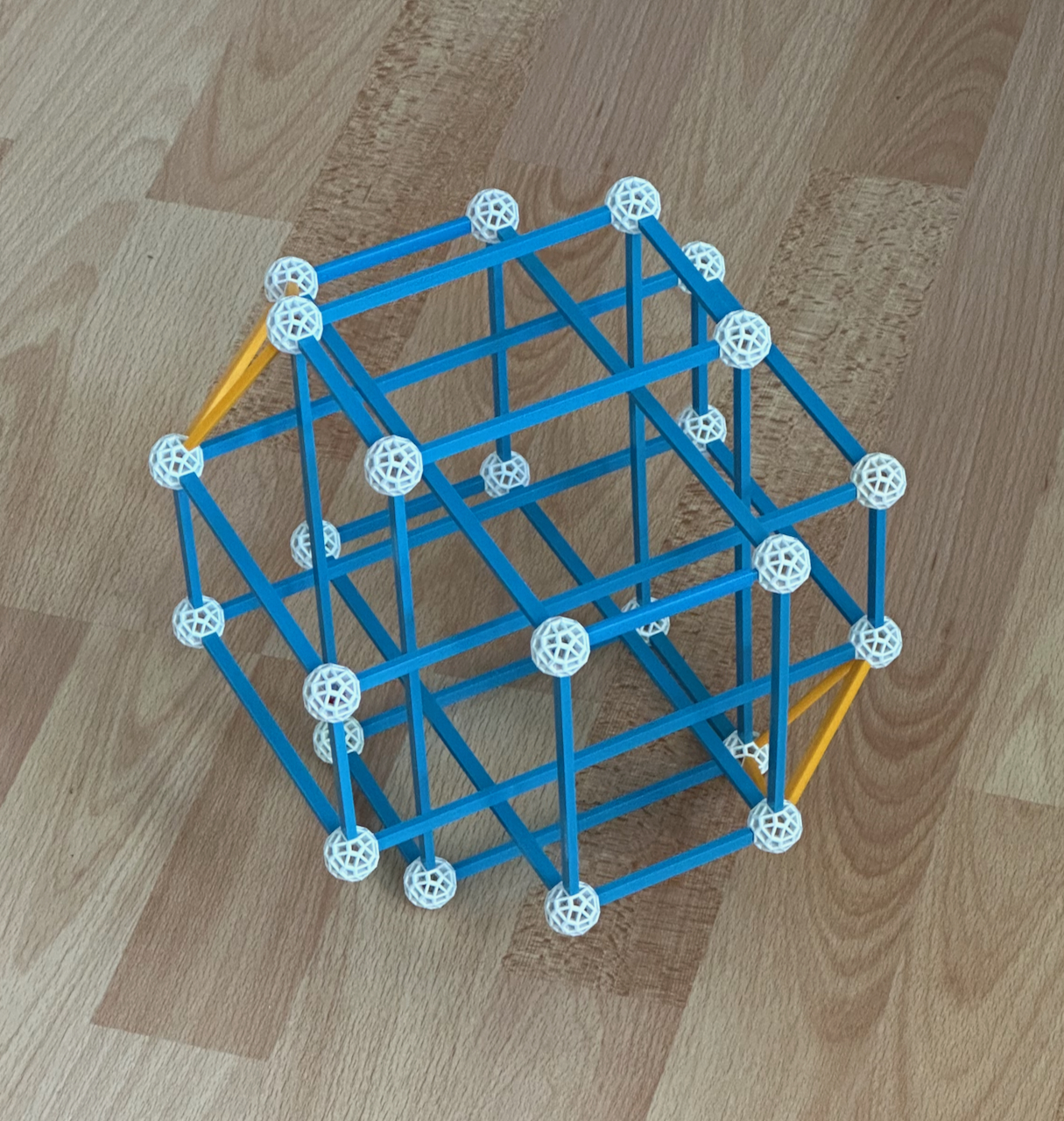
Fig. 4.4c: Three Golden cuboids in an arrangement with pyritohedric symmetry.
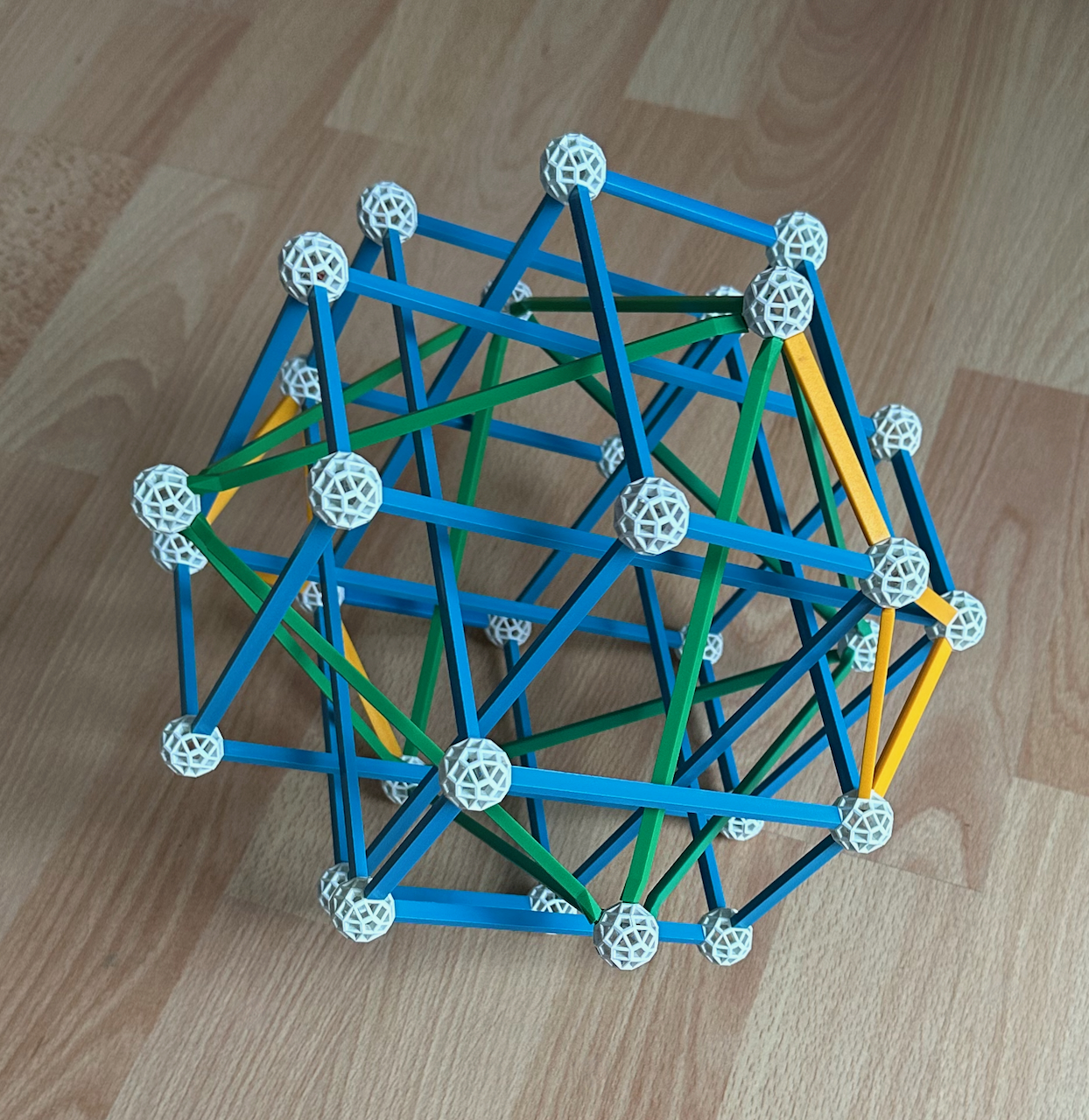
Fig. 4.4d: To the previous model, we add an Octahedron.
In Fig. 4.4c, we arrange three Golden cuboids with a pyritohedric arrangement, similar to
that of Figs. 4.2 and 4.3c. Because the radials would intersect with the long edges of the
cuboids, they are not represented. To secure the cuboids in place, we added B1 struts (the
smaller edge of the cuboids themselves), for visibility we chose these to be yellow. This
highlights the fact that the smaller edge of the Golden cuboids is the distance between
their vertices in this arrangement. The model has 3 × 8 = 24 vertices.
To the previous model, we add in Fig. 4.4c an Octahedron, which has G2 edges and, had we
chosen to do so, would also have B2 radials, like the Golden cuboids. This is also secured
in place by yellow B1 struts. The number of vertices is now 24 + 6 = 30. If the radials of
the Golden cuboids and the Octahedron were in place, they would correspond to the 30
rectangular holes of the central connector. Thus, the vertices of this figure have the
arrangement of an Icosidodecahedron. From this figure, it is easy to calculate the vertex
coordinates of this polyhedron.
Quintuplicating this model, we obtain the model in Fig. 4.12.
To summarise: the model in Fig. 4.2 shows the distribution of vertices connected to the
centre by red struts (on the 5-fold symmetry axes of the central connector, i.e., the
vertices of the Icosahedron), the model in Fig. 4.3c shows the distribution of vertices
connected to the centre by yellow struts (on the 3-fold symmetry axes of the central
connector, i.e., the vertices of the Dodecahedron) and the model in Fig. 4.4d shows the
distribution of vertices connected to the centre by blue struts (on the 2-fold symmetry
axes of the central connector, i.e., the vertices of the Icosidodecahedron). All three are
quintuplicated below in the models of these polyhedra and their facetings.
As discussed before, for the quasi-regular polyhedra, R0 and R1 are
the same as for their equatorial Polygons. For all the polyhedra above, these values can
be used to calculate the distances of the centres of the faces to the centre of the
polyhedron (R2):
R2 = √ (R02 − R0, face2) or R2 = √ (R12 − R1, face2),
where R0, face or R1, face are now the polygonal values listed in
Table 1.
Stellating and faceting the Platonic solids
In what follows, we depict how many of the polyhedra depicted by the paper models above -
especially the star polyhedra - relate to the convex polyhedra by stellation and faceting.
For the stellations we will use stellation diagrams; also
represented using the Zometool. The real vertices are indicated by the white balls; false
vertices (where edges intersect, but don't end) appear in other colours. For the
facetings, the only real vertices (of the outer polyhedron, which is the convex hull of
all objects further in) will be depicted in black, false vertices appear in other colours.
The facial plane coincidences in the models showing stellations correspond to the vertex
coincidences in the models showing facetings. Most models with icosahedral symmetry use
size 3 struts.
Incidentally (as this was not my initial intention), these models have proven to be quite
useful for understanding the polychora and polychoron compounds that will be discussed in
the subsequent pages!
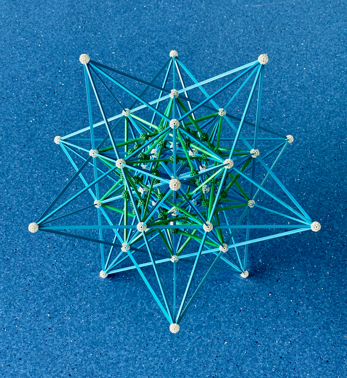
In Fig. 4.5a, we show the stellation diagram of the Octahedron. The inner Triangle is the
face of the Octahedron. The outer dual Triangle, with edges that are parallel to those of
the inner Traingle but twice as long, is the face of its only stellation, the Compound of
two tetrahedra (Fig. 3.8a). This type of stellation is called a "greatening". Expanding
all faces of the Octahedron as in the stellation diagram, we obtain (in Fig. 4.5b, on the
left) a model of the Octahedron (light blue) and the Compound of two tetrahedra (green).
On the right is the dual of the previous model, showing the Cube (in yellow) and further
in, with the same vertex arrangement, the Compound of two tetrahedra (green); this also
appears here because it is self-dual.
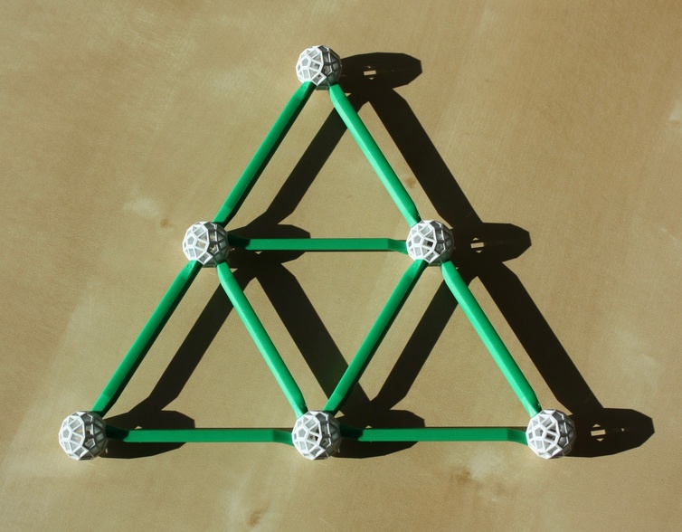
Fig. 4.5a: The stellation diagram of the Octahedron.
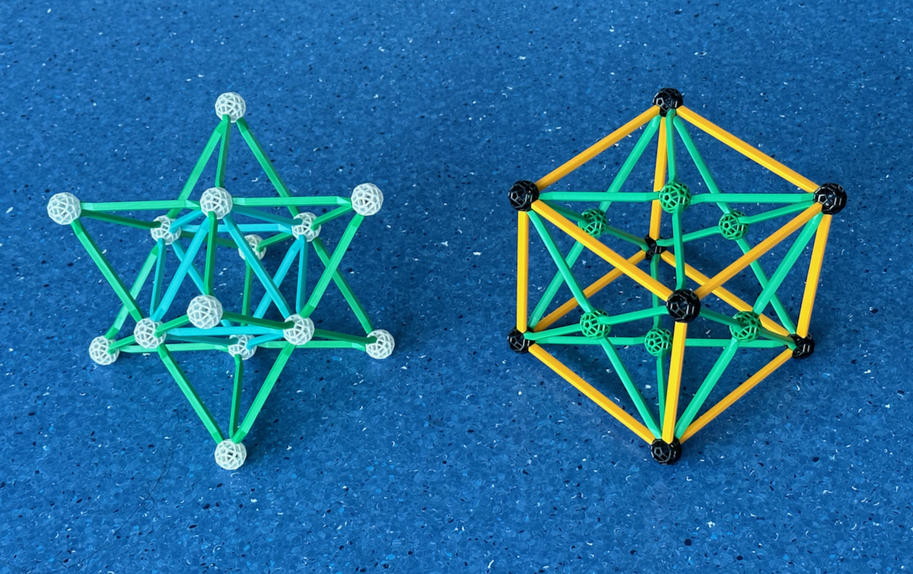
Fig. 4.5b: Left: The Octahedron and its stellation, the Compound of two tetrahedra. Right:
The dual, showing the Cube and further in the Compound of two tetrahedra.
The models in Fig. 4.5b follow the colour scheme of Fig. 4.1b, and represent the three
medial polyhedra in that model. We cannot invert the relations because there are no
stellations of the Cube, therefore no facetings of the Octahedron. On the right, note how
the Compound of two tetrahedra has all the vertex figures of the Cube that circumscribes
it. Also, all edges of that model belong to six yellow rectangles (Fig. 2.2), which are
perpendicular to the 6 axes of 2-fold symmetry of the model and lie between opposite Cubic
edges.
***
The more complex models below continue the same theme of stellations and facetings. One
common characteristic is that the inner and outer polyhedra are isomorphic to each other.
We start with the stellations of the Dodecahedron and the facetings of the Icosahedron.
Here we can represent all stellations and facetings with relatively simple models! In Fig.
4.6a, we represent the stellation diagram of the Dodecahedron; its face is the inner
Pentagon. The inner Pentagram, with edge length 2φ +1 = φ3 times
that of the inner Pentagon, is the face of the Stellated dodecahedron. The outer Pentagon
- a φ + 1 = φ2 larger dual of the inner Pentagon - is the face of the
Great dodecahedron, and the outer Pentagram - a φ2 larger dual of the inner
Pentagram - is the face of the Great stellated dodecahedron. In Fig. 4.6b, we extend the
12 faces of the Dodecahedron as in Fig. 4.6a, obtaining the four stellations of the
Dodecahedron (see Fig. 3.5a, blue rectangle in Diagram Ib).
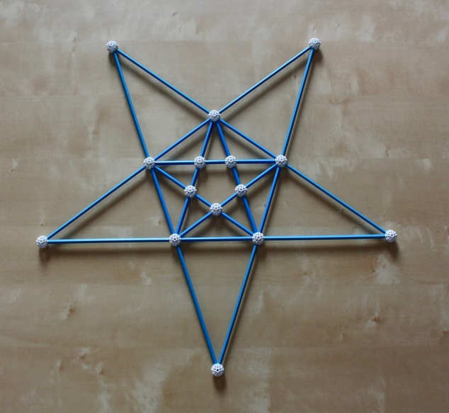
Fig. 4.6a: This is the stellation diagram of the Dodecahedron.
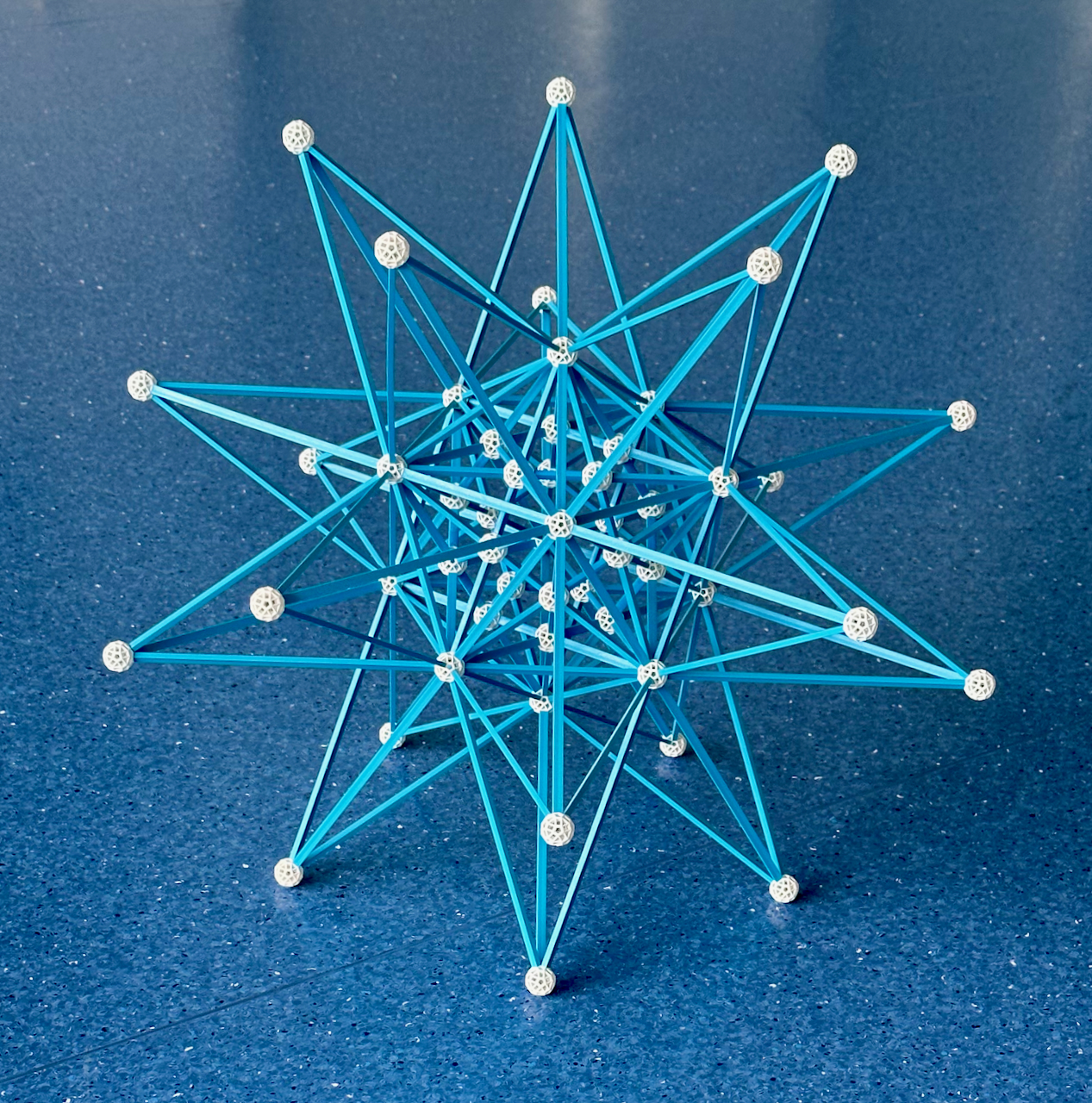
Fig. 4.6b: The four stellations of the Dodecahedron.

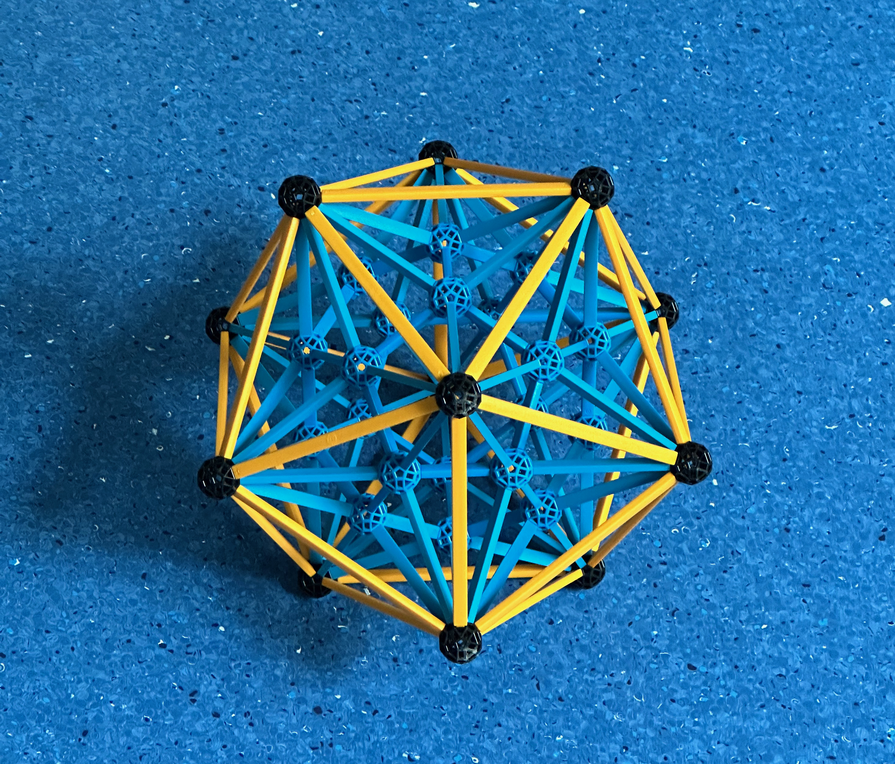
Fig. 4.6c: In this model, the dual of the model in Fig. 4.6b, we represent the four
facetings of the Icosahedron.
In Fig. 4.6c, we represent the four facetings of the Icosahedron (see Fig. 3.5a and green
rectangle in Diagram Ib), which is polyhedron in yellow B2 struts. Also represented, with
the same edge arrangement but pentagonal faces, is the Great dodecahedron. Further in, in
blue, is the Stellated dodecahedron. Finally, the innermost polyhedron, with the same edge
and vertex arrangement of the Stellated dodecahedron but with triangular faces is the
Great icosahedron. The sides of the Pentagrammic faces of the Stellated dodecahedron (in
blue) are the diagonals of the Pentagonal faces of the Great dodecahedron (in yellow),
being therefore φ times longer.
All the vertices are connected to the vertex figures of the four polyhedra by their edges,
those vertex figures are highlighted by the edges of the full set of polyhedra: for the
Icosahedron, it is the yellow Pentagon around each vertex, for the Great Dodecahedron it
is the blue Pentagram under each vertex, for the Stellated dodecahedron, it is the yellow
Pentagon around the opposite vertex, and for the Great icosahedron it is the blue
Pentagram under the opposite vertex. These vertex figures/faces are the duals of the
faces/vertex figures in Fig. 4.6b.
As mentioned above, this model is the quintuplication of the model in Fig. 4.2, minus the
red radials. This means that all edges belong to 15 Golden rectangles, which given their
symmetry must be perpendicular to the 15 axes of 2-fold symmetry, they therefore appear
halfway between opposite edges of each polyhedron. Their unit edges, here in yellow, are
those of the Icosahedron / Great dodecahedron, the φ edges (here in blue) are those of
Stellated dodecahedron / Great icosahedron.
One interesting characteristic of the model in Fig. 4.6c is that it has the same edges as
the model in Fig. 4.6b, except for the absence of the outer layer. Also, for the models in
4.6b and 4.6c, the edges of the two outer polyhedra are perpendicular to the edges of the
two inner polyhedra immediately below them, reflecting the duality of the Stellated
dodecahedron and Great dodecahedron.
***
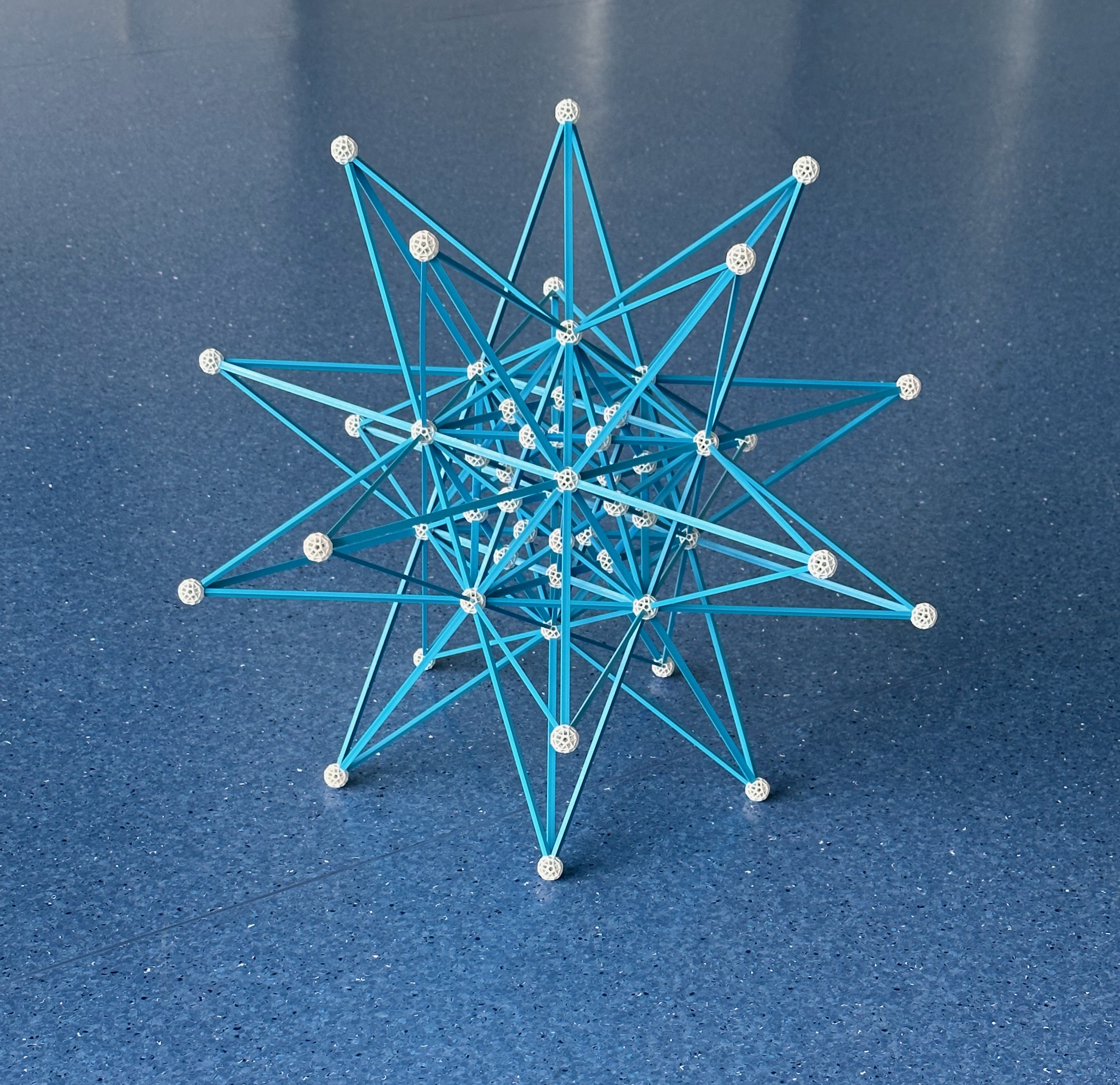
We now continue with the stellations of the Icosahedron. In Fig. 4.7a we present an
incomplete stellation diagram of the Icosahedron, representing four of the figures that
can be built with a small model in the Zometool. The inner blue Triangle is the face of
the Icosahedron, the outer φ4 larger dual Triangle is a face of the Great
icosahedron (see Fig. 3.5a). The green Triangle is a face of the Compound of five
tetrahedra (see Fig. 3.8a). An intermediate figure, the propeller tripod (on lower left of
Fig. 2.3e) is the face of the self-dual excavated dodecahedron. In
Fig. 4.7b, we present a model with these four stellations. Other stellations of the
Icosahedron we have seen in the previous page are either not Zomable, like the triambic
icosahedra and compound of ten Tetrahedra, or cannot be built at this scale, like the
Compound of five Octahedra.
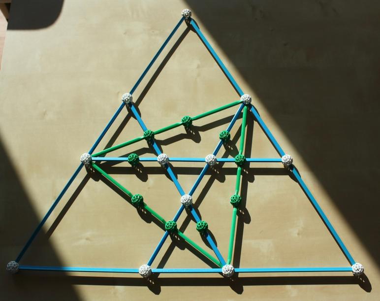
Fig. 4.7a: An incomplete stellation diagram of the Icosahedron, representing four of the
figures that can be built with a small model in the Zometool.

Fig. 4.7b: Extending the 20 faces of the Icosahedron as shown above, we have the four
stellations of the Icosahedron mentioned above.
The Compound of ten tetrahedra (also in Fig. 3.8a) is also a stellation of the
Icosahedron, but it is not Zomable, as it would require two green struts to connect to the
same holes.
We continue with the facetings of the Dodecahedron. The model below is not strictly a dual
of the previous one because it also includes the edges of the ditrigonal polyhedra, which
coincide with the edges of the Compound of five cubes. It does include the edges of the
self-dual excavated dodecahedron, but these appear in different colours, depending on
whether they coincide with edges of the Dodecahedron (white) or the Great stellated
dodecahedron (yellow). The faces of this polyhedron (the propeller tripods) also appear in
the model.
The edges of the Compound of five cubes (Fig. 3.8b) and the ditrigonal polyhedra (Fig.
3.7, here in blue) are the diagonals of Pentagonal faces of the outer Dodecahedron that
circumscribe them (in white), being therefore φ times longer. Similarly, the sides of
the Pentagrammic faces of the Great stellated dodecahedron (Fig. 3.5a, here in yellow) are
the diagonals of the Pentagonal faces of the ditrigonal polyhedra that circumscribe them,
being therefore φ times longer again. The planes of these Pentagon-Pentagram pairs are
parallel to each other, these sets of faces have otherwise identical orientations. The
edges of the Compound of five tetrahedra (Fig. 3.8a, here in green) are the diagonals of
the faces of the Compound of five cubes.
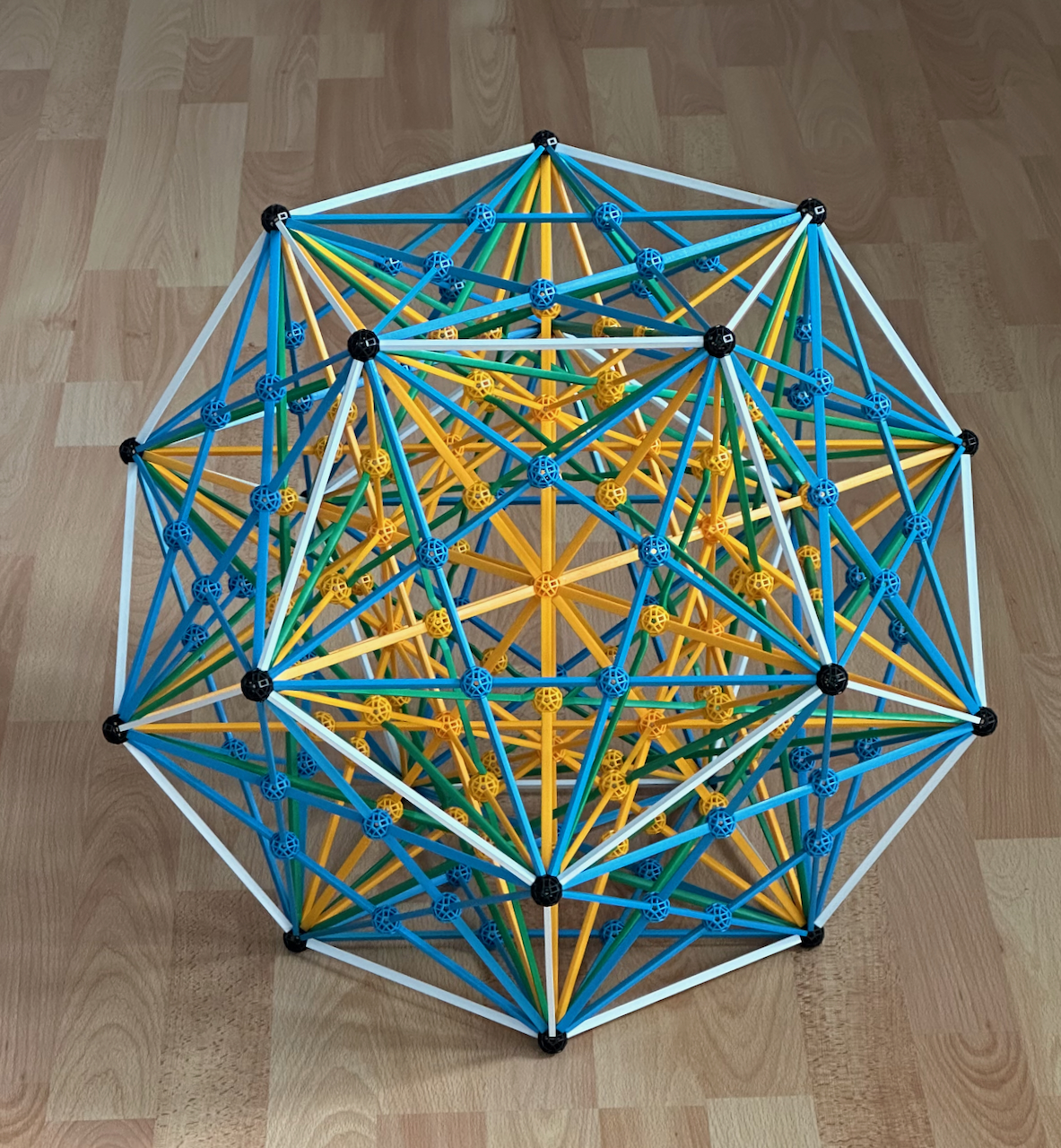
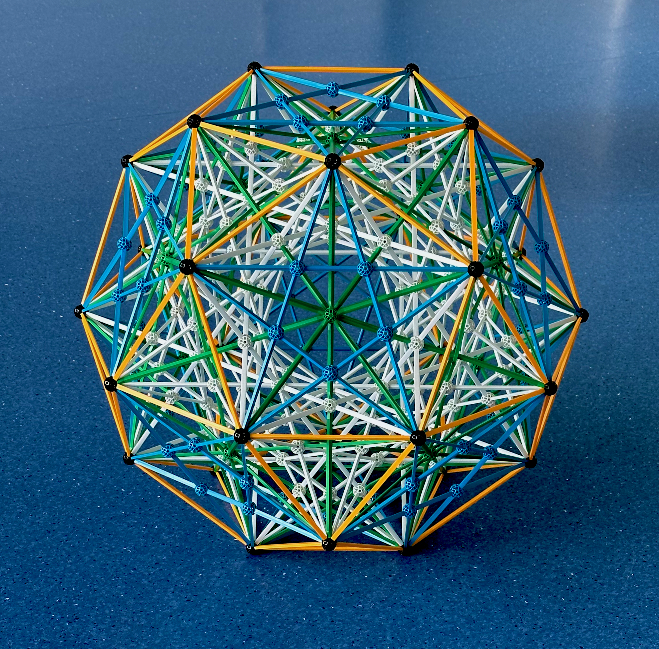
Fig. 4.8: This model represents facetings of the Dodecahedron, this is the outer
polyhedron represented by the white B3 struts, the convex hull that circumscribes all
other polyhedra further in that were represented by paper models.
As mentioned above, this model is the quintuplication of the model in Fig. 4.3c, minus the
yellow radials. This means that all edges belong to five cubes (the unit edges, here in
blue), five Tetrahedra (the √2 edges, here in green) and fifteen long yellow
rectangles, of which the 1/φ and φ edges are those of the Dodecahedron (in white)
and Great stellated dodecahedron (in yellow). Given their rectangular symmetry, the Long
Yellow rectangles must be perpendicular to the 15 axes of 2-fold symmetry, they therefore
appear halfway between opposite edges of the Dodecahedron and great stellated
dodecahedron.
Around each vertex, the blue Triangles (faces of the Small ditrigonal icosidodecahedron)
trace the vertex figures of the Dodecahedron and, near the opposite vertex, of the Great
stellated dodecahedron, being connected to them by the edges of these Polyhedra. You can
also see how the vertex figures of the ditrigonal polyhedra (the ditrigonal hexagons in
Fig. 2.3e,) are traced below each vertex by the edges of the Dodecahedron, Great stellated
dodecahedron and the ditrigonal polyhedra. One of these vertex figures, the propeller
tripod, is the face of the excavated dodecahedron. The vertex figures of the Cubes are
highlighted by the edges of the tetrahedra; however, because the compound does not have
full icosahedral symmetry (because of the Compound of five tetrahedra), not all vertex
figures of all the Cubes are represented in the model.
We now show the construction process, starting from the polyhedron further in, then adding
successive layers.
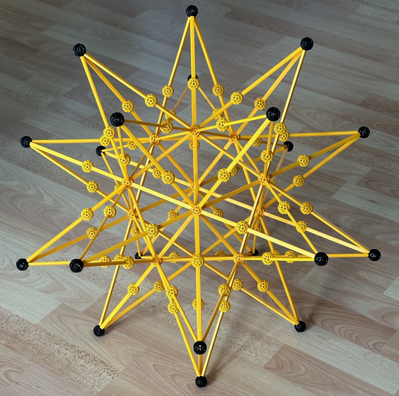
Fig. 4.8a: At the centre of the previous model, in yellow B1 and B2 struts, is the Great
stellated dodecahedron.
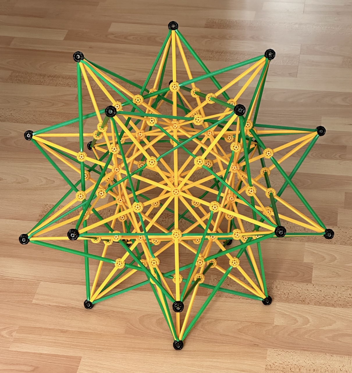
Fig. 4.8b: The green struts represent the Compound of five tetrahedra.
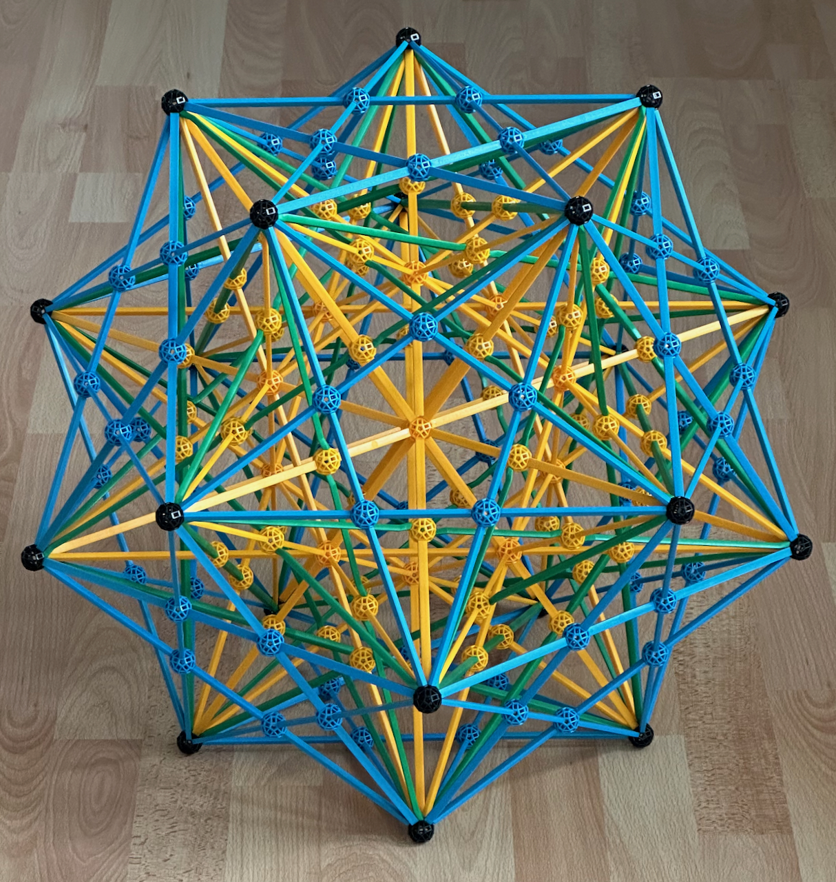
Fig. 4.8c: The blue B1/B2 struts represent the ditrigonal polyhedra and the Compound of
five cubes, all of which share the same edge arrangement.
If we made the model in Fig. 4.8 a strict dual of the model in Fig. 4.7b (i.e., not
including the blue struts), then the model would share the same edges of the model in Fig.
4.7b, apart from the outer layer. This is analogous to the relation between the models in
Fig. 4.6b and 4.6c.
Stellating and faceting the quasi-regular solids
As discussed above, all edges of the regular, quasi-regular and partially regular
polyhedra and their compounds can be represented with G and B struts. The Y and R struts
have only been used for the radials of the models in the latter figures.
However, this is not the case for the rhombic solids. In Fig. 3.3b and 3.3c, we depicted
compounds of dual Platonic solids; their edges intersecting at 90 degrees at their
midpoints, represented by black balls. In Fig. 4.9, we show pairs of these intersecting
edges. Since the rhombic polyhedra are the convex hulls of the compounds of dual Platonic
solids, their faces are in the same plane as these two intersecting edges, and must be the
smallest polygons to fully circumscribe them. These faces are, respectively, Yellow and
Golden rhombuses, with the same edge colours (Y and R) and in this case dimensions as
those rhombuses in Figs. 2.5a and 2.5b. Compare these figures with the Yellow and Golden
rectangles in Figs. 2.2b and 2.2d: doing this, one understands why these struts represent
at the same time the radials of the Cube and Icosahedron (Figs. 4.2 and 4.3a) and the
rhombic polyhedra.

Fig. 4.9, Top: the intersecting edges of the Cube (B1) and Octahedron (G1) in Fig. 3.3b
can be inscribed in a Yellow rhombus (see Fig. 2.5a). Bottom: the intersecting edges of
the Dodecahedron (B1) and Icosahedron (B2) in Fig. 3.3c can be inscribed in a Golden
rhombus (see Fig. 2.5b).
We now show models of these rhombic polyhedra (with Y and R struts) and their stellations,
and also duals models of these, showing facetings of their duals, the Cuboctahedron and
Icosidodecahedron. Before each pair of models, we show, as above, stellation diagrams for
the isohedral polyhedra to be stellated (the rhombic solids).
We start in Fig. 4.10a with a stellation of the Rhombic dodecahedron and a facetings of
its dual, the Cuboctahedron. There are four stellations, with vertices indicated by the
connector colours: the rhombic dodecahedron (black balls), first stellation (blue balls),
second stellation (yellow balls) and third stellation (green balls). In Fig. 4.10b we
represent the Rhombic dodecahedron and its first stellation. The latter object is known as
"Escher's
solid". Like the Rhombic dodecahedron, this particular shape can also fill space. It is composed of three Square bipyramids, with Square bases in blue
and yellow struts representing all other edges. I call these Yellow bipyramids.

Fig. 4.10a: This is the stellation diagram of the Rhombic dodecahedron.

Fig. 4.10b: The Rhombic dodecahedron and its first stellation.

Fig. 4.10c: The dual of the model in Fig. 4.10b, the Cuboctahedron and, further in, its
first faceting.
In Fig. 4.10c, we present the dual of the model in Fig. 4.10b, the Cuboctahedron and its
first faceting. Note all edges the last figure belong to a set of three Yellow prisms
(Fig. 4.4a). These are the duals of the three yellow bipyramids in Fig. 4.10b. Their
longer edges are the diagonals of the Square faces of the Cuboctahedron. The 3 × 8 =
24 vertices coincide by twos with the 12 vertices of the outer Cuboctahedron. The
diagonals of these three Yellow prisms (shown in Fig. 4.4a) are the Zomable radials of all
four equatorial Hexagons in this model (see Fig. 2.3c). However, although they are clearly
Zomable, the radials are not represented here. In the models above, we could have shown
additional stellations of the Rhombic dodecahedron, but their dual facetings of the
Cuboctahedron are not Zomable.
An interesting thing about the dual objects in Figs. 4.10b and c is that they have an
identical vertex arrangement, which coincides with that of the Cuboctahedron. This means,
by duality, that they have an identical arrangement of facial planes; the faces lie
directly under each vertex of the Coboctahedron!
***
Below, we show a model of the four isotoxal stellations of the rhombic triacontahedron.
For more on them and instructions on how to build them, and many more stellations of the
Rhombic triacontahedron, look here.
In Fig. 4.11a, we show, within the inner region of the stellation diagram of the Rhombic
triacontahedron (shown in full detail here) the faces of its four isotoxal stellations,
for which we have built paper models above. The inner Golden rhombus (in red, see also
Fig. 2.4b) is one of the 30 faces of the Rhombic triacontahedron itself (Fig. 3.4). The
Long yellow rhombus (Fig. 2.4c) is one of the 30 faces of the Medial rhombic
triacontahedron (see Fig. 3.6a). The blue Square is one of the 30 faces of the Compound of
5 cubes (Fig. 3.8b). The outer Golden rhombus, which is 2φ + 1 = φ3
times larger than the inner red Rhombus, is one of the 30 faces of the Great rhombic
triacontahedron (Fig. 3.6a). In Fig. 4.11b, we extend the 30 faces of the Rhombic
triacontahedron as in Fig. 4.11a, to obtain the Rhombic triacontahedron and its isotoxal
stellations.

Fig. 4.11a: Part of the net of the Rhombic triacontahedron, showing the faces of its
isotoxal stellations.
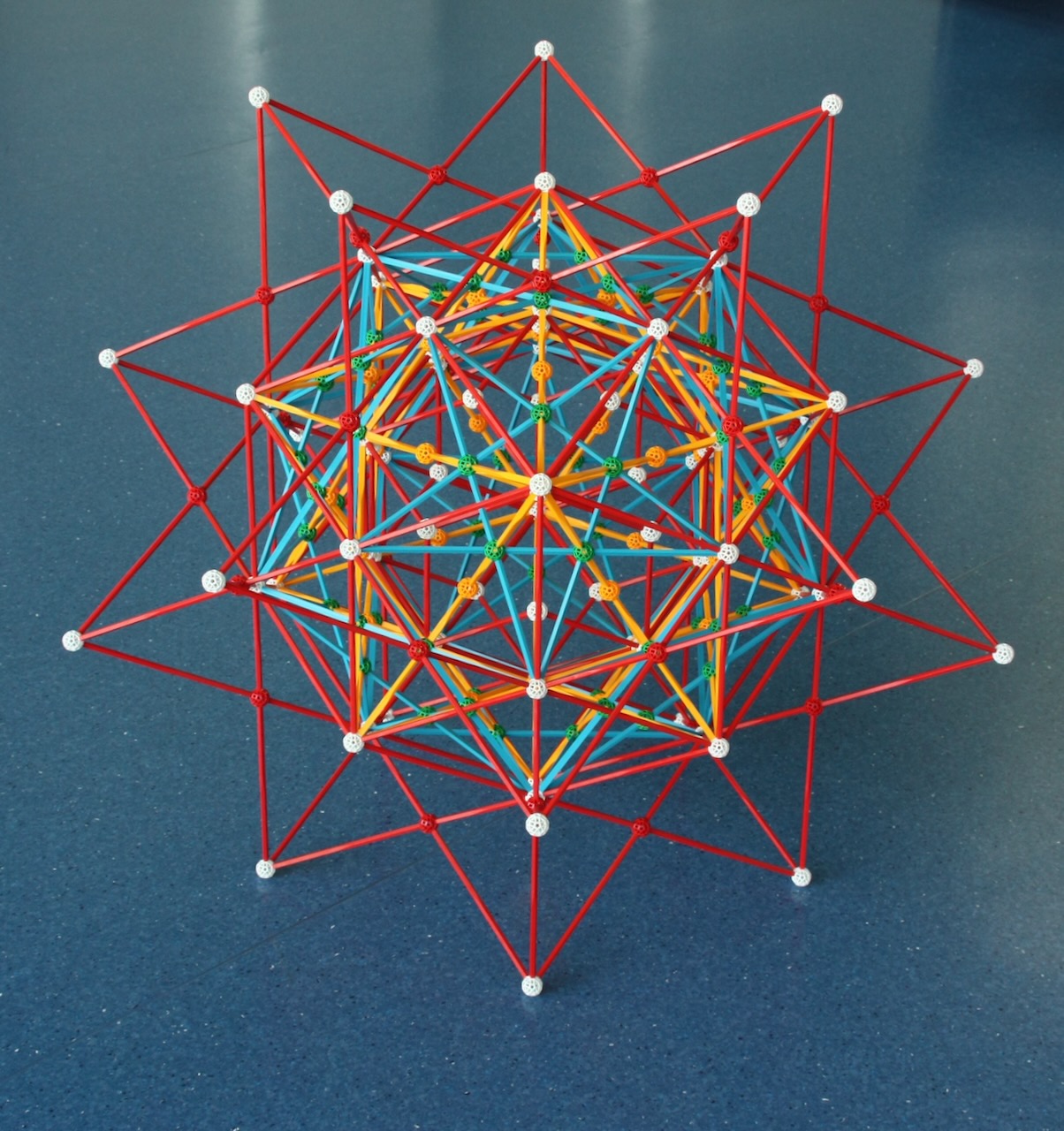
Fig. 4.11b: Extending the 30 faces of the Rhombic triacontahedron as in Fig. 4.11a, we
obtain the Rhombic triacontahedron and its isotoxal stellations.
We now show the dual model, the Icosidodecahedron (the outer shape in yellow B3 struts)
and its isotoxal facetings. In this model we can see that the sides of the Pentagrammic
faces of the Dodecadodecahedron (Fig. 3.6a, here in blue) are the diagonals of Pentagonal
faces of the outer Icosidodecahedron that circumscribe them (Fig. 3.4, here in yellow),
being therefore φ times longer. Similarly, the sides of the Pentagrammic faces of the
Great icosidodecahedron (Fig. 3.6a, here in white) are the diagonals of the Pentagonal
faces of the Dodecadodecahedron that circumscribe them, being therefore φ times longer
again. The planes of these Pentagon-Pentagram pairs are parallel to each other but these
sets of faces have dual orientations. Also, the planes of the Triangular faces of the
Icosidodecahedron are parallel to those of the Triangular faces of the Great
icosidodecahedron, but these Triangles are also in dual orientations.

Fig. 4.12: The Icosidodecahedron and its isotoxal facetings.
As mentioned above, this model is the quintuplication of the model in Fig. 4.4d. This
means that there are now five Octahedra and 15 Golden cuboids aligned with the 15 axes of
2-fold symmetry. All vertices connect to an Octahedron and to four different Golden
cuboids. The 1 / φ edges of the Golden cuboids are those of the Icosidodecahedron,
their "unit" edges, which correspond to the length of their radials, are those of the
Dodecadodecahedron - which is radially equilateral - and their φ edges are those of
the Great icosidodecahedron. Note that all vertex figures of all polyhedra in the model
(the duals of the faces of the polyhedra in Fig. 4.11b) are represented in the model. For
the three polyhedra with rectangular vertex figures that touch each vertex, the three
vertex figures are represented by three different faces of three different Golden cuboids;
these three rectangles appear directly under that vertex at three different levels that
are connected to that vertex by the edges of the three respective polyhedra.
All objects depicted have equatorial polygons, which account for all edges: 6 equatorial
Decagons of the Icosidodecahedron (in Yellow) and Decagrams of the Great icosidodecahedron
(in white), which are perpendicular to the 6 axes of 5-fold Icosahedral symmetry of the
model and lie between opposite pairs of Pentagonal and Pentagrammic faces, the 10
equatorial Hexagons of the Dodecadodecahedron (in blue), which are perpendicular to the 10
axes of 3-fold symmetry of the model and lie between opposite pairs of Triangular faces,
and the 15 equatorial Squares of the Compound of five octahedra (in green), which are
perpendicular to the 15 axes of 2-fold symmetry of the model and lie between opposite
pairs of vertices. Of course, these equatorial polygons correspond to the equatorial rings
of faces of the dual polyhedra in Fig. 4.11b.
We now show the construction process, starting from the polyhedron further in, then adding
successive layers.
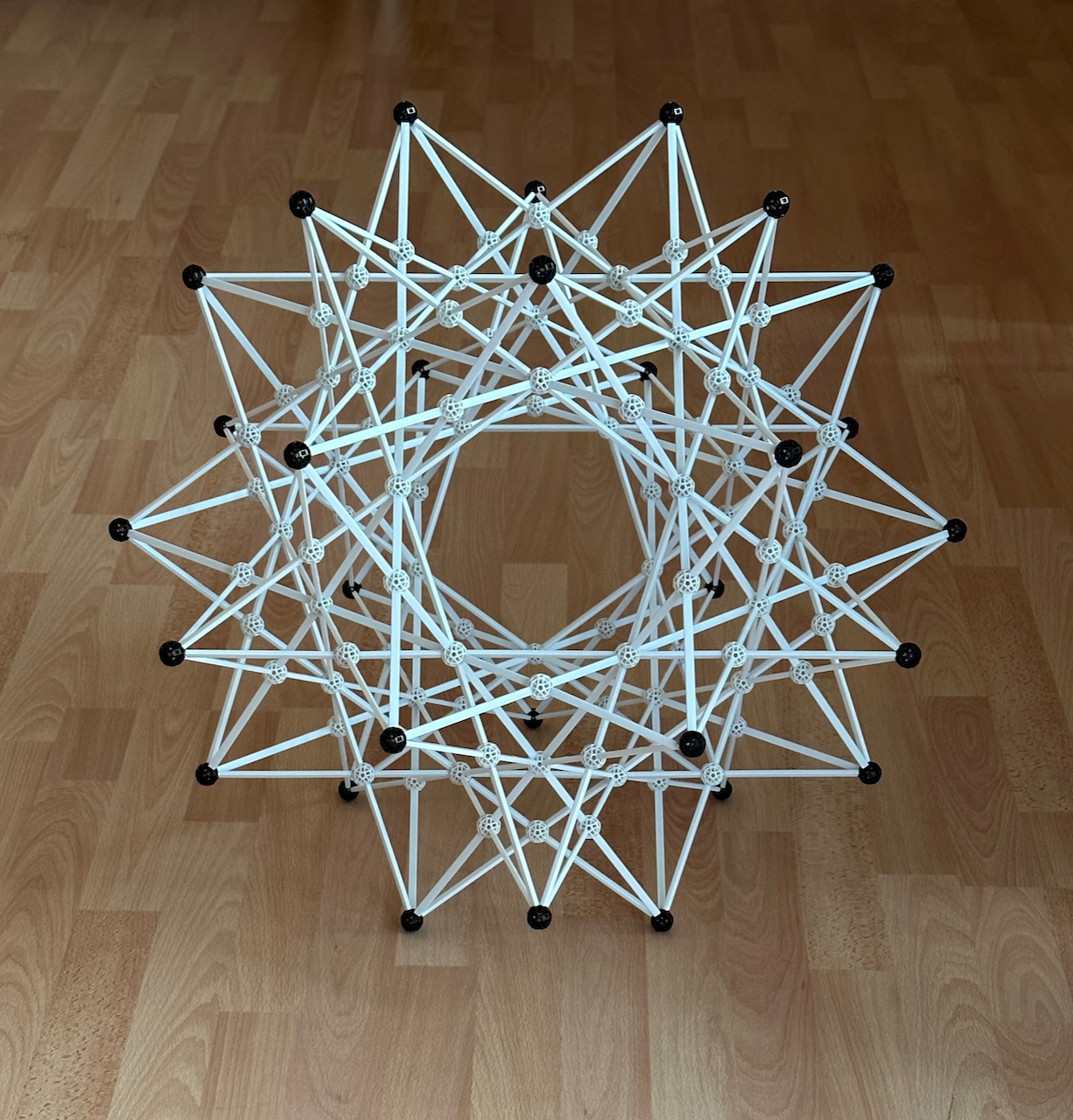
Fig. 4.12a: At the centre of the model is the Great icosidodecahedron, in white B1 and B2
struts.
Important: If you build the model in Fig. 4.12a, you'll notice an interesting fact:
At the centre of the model, you will see an Icosidodecahedron with "false" white vertices
located directly under the outer real black vertices, with an arrangement that is φ
times smaller. This fact is not obvious from the paper model in Fig. 3.6a.
The reason for this is that the edges of the Great icosidodecahedron are obtained by
extending the edges of an Icosidodecahedron: the 12 Pentagons of the Icosidodecahedron
were stellated into 12 isomorphic Pentagrams with a φ3 times larger side
(see Fig. 2.6a) and its 6 equatorial Decagons into 6 isomorphic equatorial Decagrams, also
with a φ3 times larger side (see Fig. 2.8b). As we've seen in the study of the sizes of Polygons, the
vertices of a Decagram are located right above the vertices of the Decagon they stellate
(Fig. 2.8b), with an arrangement that is φ times larger (Fig. 2.8c).
The fact that these are equatorial polygons of the inner Icosidodecahedron and Great
icosidodecahedron imply that the vertices of the latter are also located right above those
of the former, also with an arrangement φ times larger, as we see in the model. This
fact will have important implications for understanding some of the regular star
polychora.
Fig. 2.8c can thus be seen as a cut of Fig. 4.12 along its equatorial Decagons. These
correspond to the outer Decagon in Fig. 2.8c. The equatorial Decagram of the inscribed
Great icosidodecahedron (Fig. 4.12a) is the inscribed Decagram in Fig. 2.8c.
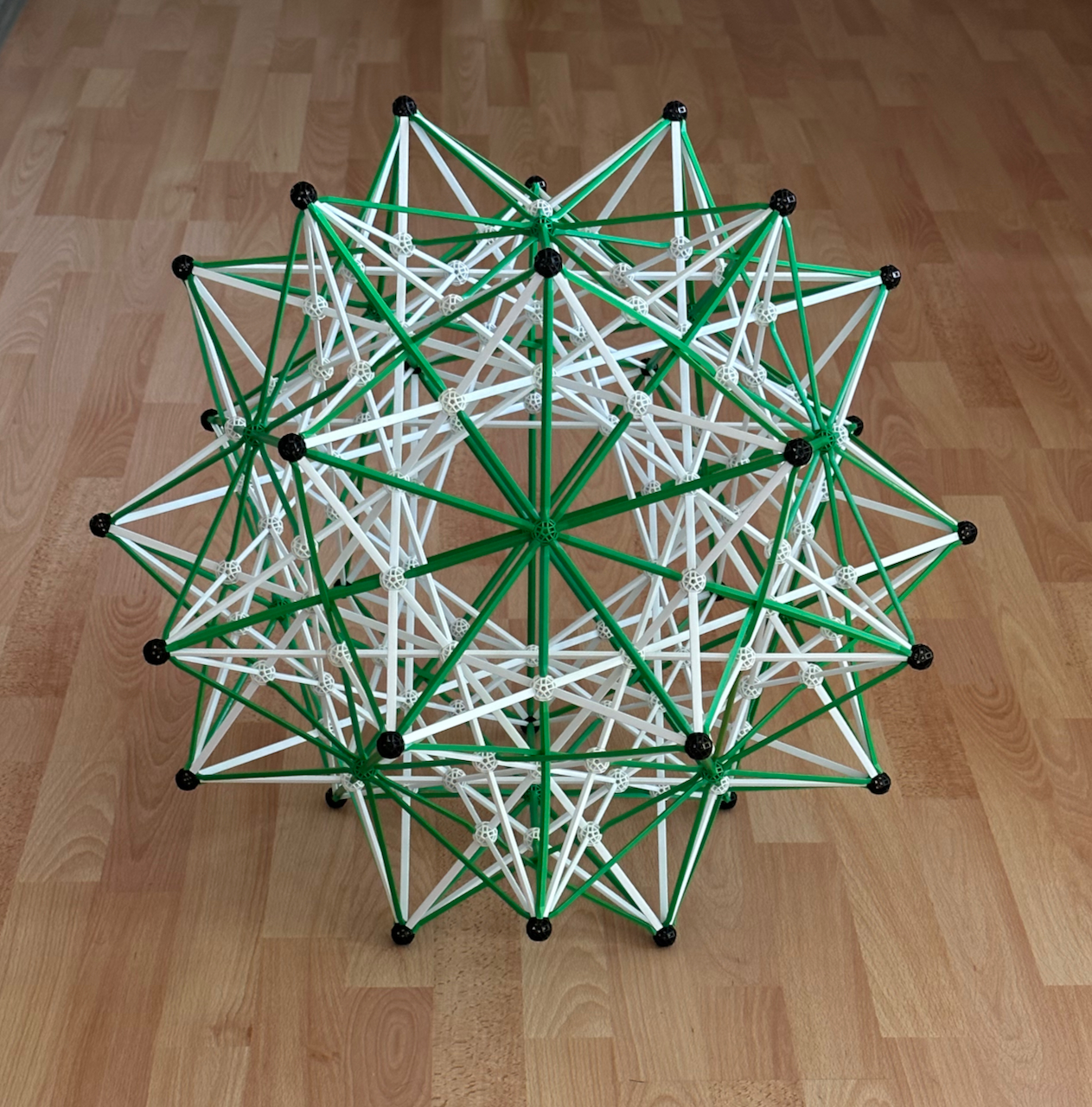
Fig. 4.12b: Just outside the Great icosidodecahedron is the Compound of five octahedra, in
green G2 and G3 struts. Note the 3-intersections of some of the G3 struts in the 3-fold
symmetry axes, where they have to bend a bit.
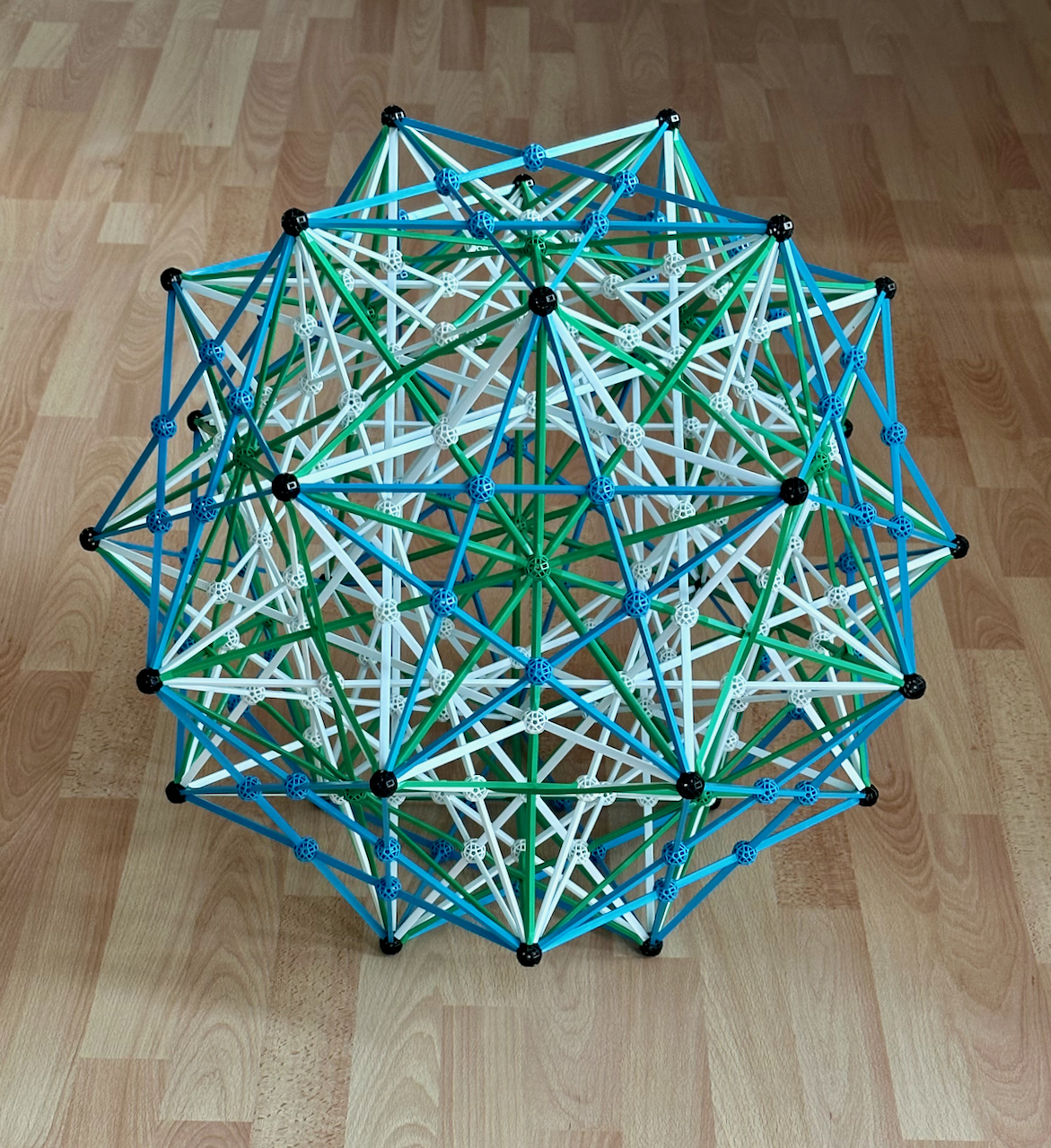
Fig. 4.12c: Just above the Compound of five octahedra is the Dodecadodecahedron in blue B1
and B2 struts.
One could also make models with the stellations of the Coboctahedron and Icosahedron and
the facetings of the Rhombic dodecahedron and triacontahedron, but none of those
stellations is isotoxal.
One last word about the models in this page. They are the closest in the whole site to
artistic objects: one can choose which combinations of polyhedra to show, and their sizes
and orientations relative to each other, furthermore we have some freedom in the choice of
colours. The models in Figs. 4.1a and b are in my opinion elegant works of art. Regarding
the other models, although they are more didactical, they can also be very pleasing. I am
particularly happy with those in Figs. 4.7b, 4.11b and 4.12. The model in Fig. 4.8c is
also quite striking!
Paulo's polytope site / Next: Polychora