
| Type | HEMT, cooled |
|---|---|
| Channels | 14 in 7 beams |
| Receiver Noise Temperature | 10 K - 20 K (see below) |
| Frequency Range | 1260 - 1510 MHz |
| Bandwidth RF-Filters | 1260 – 1510 MHz 1380 – 1427 MHz |
| Polarization | Centre Horn: LHC and RHC Outer Horns: Linear H and V |
| Calibration | Noise Diode VTO: yes |
| Phaseshifter | no |
| Feed | Coaxial Horn |
| Beam separation | 0.25° = 1,6 beam widths |
| 1. IF | 30 - 280 MHz |
| 1. Oscillator | ULO1 or LO, upper side band, 1230 MHz |

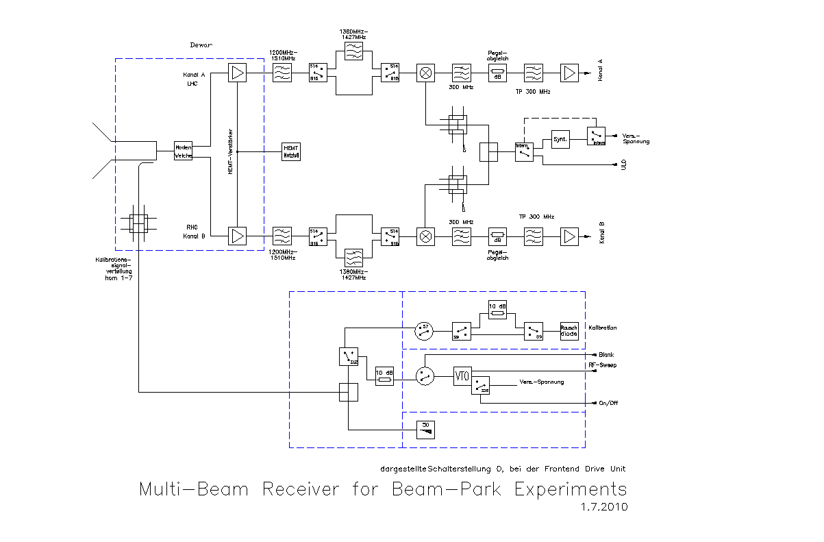
This is a receiver for the 21 cm Radioastronomy band. It is primarily built for the European Space Operation Centre (ESOC) for space debris measurements in Beam-Park Experiments (BPE). The Project is entitled „Multi-Beam Receiver for Beam-Park Experiments“, Contract No. 16173/02/D/HK, and pays all the material cost of the receiver while manpower is provided by MPIfR. Beam Park Experiments for space debris measurements are performed by a bistatic radar arrangement with the antenna beams parked at one certain point at the sky. The transmitting station is the TIRA antenna of FGAN in Wachtberg – Werthofen near Bonn, which is 21 km line of sight apart of the receiving Effelsberg telescope. In this configuration debris particles down to 9 mm diameter at 800 km to 1000 km height can be detected. This could be demonstrated in a first joint measurement in 1996: COBEAM.
A new backend was also developed for this receiver. It consists of seven commercially of the shelf dual channel sampling cards. The data is digitized with a sample rate up to 100 MHz and can be processed by a powerful FPGA. For BPE the sampled data is filed through the FPGA to a PCI system together with an accurate time stamp.
BPE are now performed on a regular basis since June 2006.
The 21 cm seven beam receiver is operated in Effelsberg and can be used for radio astronomy purpose most of the time. Two filter bandwidths are available: the protected radio astronomy band 1380 MHz to 1427 MHz and the full receiver bandwidth 1260 MHz to 1510 MHz. The centre horn has circular polarization, the outer horns are linear polarized. The horns are arranged in an hexagonal package close together. The beam footprint at the sky is shown below.

|

|
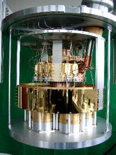
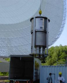
| Dewar insight | Receiver Box |
| Frequency range: |
1260 MHz - 1510 MHz GHz (S14, S15 = 0) 1380 MHz - 1427 MHz GHz (S14, S15 = 1) |
|---|---|
| ULO frequencies: |
fULO1 = fsky – 150 MHz fsky = fULO1 +150 MHz fULO2 = not used |
| IF - bandwidth: | 250 MHz at fIF = 155 MHz |


| Channel | Polarization (sky) | S14, S15 = 0: 140 MHz bandwidth | S14, S15 = 1: 47 MHz bandwidth | ||||
|---|---|---|---|---|---|---|---|
| TE /K | Tcal I/K | Tcal II/K | TE /K | Tcal I/K | Tcal II/K | ||
| 0A | LHC | 20,9 | 12,6 | 1,3 | 20,9 | 4,5 | 0,5 |
| 0B | RHC | 20,5 | 16,8 | 1,7 | 20,5 | 5,5 | 0,6 |
| 1A | V | 13,9 | 10,2 | 1,0 | 13,9 | 4,0 | 0,4 |
| 1B | H | 10,9 | 13,2 | 1,3 | 10,9 | 4,1 | 0,4 |
| 2A | V | 16,8 | 17,2 | 1,7 | 16,8 | 4,8 | 0,5 |
| 2B | H | 9,9 | 10,6 | 1,1 | 9,9 | 4,7 | 0,5 |
| 3A | V | 20,6 | 10,4 | 1,0 | 20,6 | 4,2 | 0,4 |
| 3B | H | 14,2 | 13,3 | 1,3 | 14,2 | 4,0 | 0,4 |
| 4A | V | 17,6 | 13,6 | 1,4 | 17,6 | 3,9 | 0,4 |
| 4B | H | 13,5 | 12,5 | 1,3 | 13,5 | 4,0 | 0,4 |
| 5A | V | 19,3 | 11,7 | 1,2 | 19,3 | 3,6 | 0,4 |
| 5B | H | 14,3 | 10,5 | 1,1 | 14,3 | 4,0 | 0,4 |
| 6A | V | 11,4 | 9,6 | 1,0 | 11,4 | 4,4 | 0,4 |
| 6B | H | 14,1 | 8,9 | 9,0 | 14,1 | 5,1 | 0,5 |
B. Klein, G. Bartsch, R. Keller, L. Leushacke: “Improved Systems for Bistatic Beam Park Experiments”; COSPAR Paris, July 2004