The blazar 3C345 is a strongly variable core-jet type source with a compact core responsible for most of the source radio emission, and a curved, parsec-scale jet (Zensus et al. 1995) containing enhanced emission regions (bright components) travelling along curved trajectories, with speeds of up to 20c (Zensus et al. 1995). Synchrotron spectra of the core and the nearest bright components are often peaked around 10GHz, and show a remarkable evolution. The emission from the core and the components is believed to be produced by condensations of highly-relativistic electron-positron plasma injected in the jet, and losing their energy first through the inverse-Compton mechanism (Unwin et al. 1997), and later on due to the synchrotron emission from adiabatically expanding relativistic shocks (Wardle et al. 1994; Zensus et al. 1995).
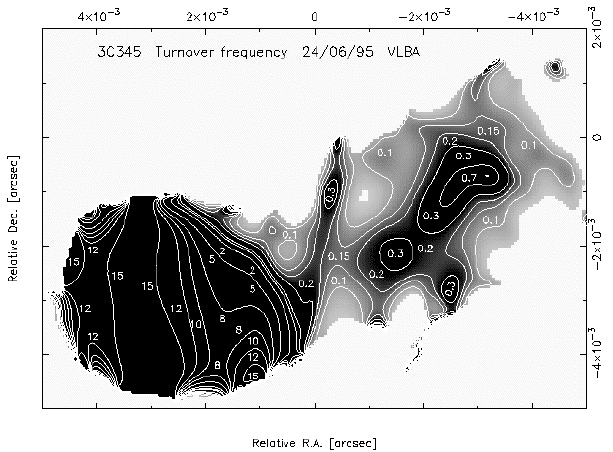
The turnover frequency mapping procedure (Lobanov 1998b) was applied to the multi-frequency VLBA observation of 3C345 made on June 24, 1995. The source was observed at 5, 8.4, 15.4, and 22.2GHz. At each frequency, there was roughly one 5 minute scan made every 20 minutes. After the correlation, the data were fringe-fitted and mapped in AIPS and DIFMAP. The turnover frequency map produced from the VLBA maps is shown in Figure 1. (Lobanov et al. 1997)

Figure 1 . Turnover frequency distribution in the extended jet of 3C\,345. The central region is saturated, for better representation of the turnover frequency variations in the jet. The contours are drawn at 0.1, 0.15, 0.2, 0.3, 0.7, 1, 2, 5, 8, 10, 12, and 15GHz. All values below 5GHz should be regarded as upper limits.
Extended jet
Almost everywhere in the extended jet shown in Figure 1, the turnover frequency is lower than 5GHz, posing a problem for both the spectral fitting and assessing the results from the fits - we therefore resort to regarding all values of the turnover frequency smaller than 5GHz as upper limits. Apparently, there are no strong shocks dominating the extended jet of 3C345 or their turnover points may have evolved rapidly due to strong adiabatic cooling. Because the derived turnover frequencies are too low, we cannot make quantitative statements about the physical conditions in the extended jet. Observations at lower frequencies (1.6, 1.4, 0.6, 0.3GHz) are required for a better understanding of the turnover frequency changes in these regions. With the available data, we can only make general comments about the gradients observed in the turnover frequency map. The bright patterns elongated along the jet ridge line may indicate the presence of an ultra-relativistic channel inside the jet (e.g. Sol et al 1989). The extended patterns seen in the jet at oblique angles to the ridge line resemble the patterns of Kelvin-Helmholtz instabilities (see Hardee et al. 1995, for the results from 3D simulations of the KH-instability driven jets). Since the turnover frequency is exceptionally sensitive to the variations of plasma speed and density, the observed patterns may reflect the velocity gradients and/or density gradients existing in the jet perturbed by the Kelvin-Helmholtz instability. However, the low frequency data are needed for making a better substantiated conclusion about the observed gradients.
Nuclear region
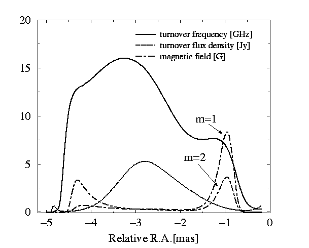
In Figure 1, there are two regions of higher turnover frequency in the nucleus of 3C345 oriented nearly transversely to the direction of the jet. These regions match fairly well the locations of the core and the closest moving feature in the jet (designated C7). The increased turnover frequency may indicate that the emission is coming from a shocked plasma. The transverse extension is then consistent with strong shocks that are likely to be oriented almost perpendicularly to the jet direction. Figure 2 shows the turnover frequency and turnover flux density profiles along the horizontal line crossing the center of the core. The core and C7 are both visible in the turnover frequency profile. The turnover flux distribution is very smooth and peaks almost precisely at the center of the core. From the turnover frequency and turnover flux distributions, we can derive the profile of magnetic field in the central region using the relations derived for the plane relativistic shocks. The magnetic field in a shock also depends on the strength of the underlying magnetic field in the location of the jet where the shock is formed. We postulate that the underlying magnetic field Bamb ~r-m, and consider the cases with m=1 and m=2. The magnetic field rises sharply, close to the outer edge of C7. This can signify the amount of plasma compression in the shock. The increased magnetic field on the opposite side (particularly visible in the Bamb ~r-2 profile) may reflect a larger electron plasma density near the jet origin. In the relativistic jets, the case Bamb ~r-1 is expected to be more likely. A somewhat high value of the magnetic field in C7 (BC7 =8.5G) in this case may also be caused by possible errors in the estimates of the core magnetic field. However, the derived shape of the magnetic field profile is consistent with C7 being a strong shock embedded in the jet of 3C345.

Figure 2. Profiles of turnover frequency, turnover flux density, and magnetic field along the line crossing the center of the core. The underlying magnetic field decreases along the jet as r-m.